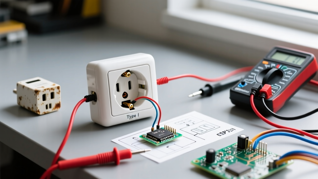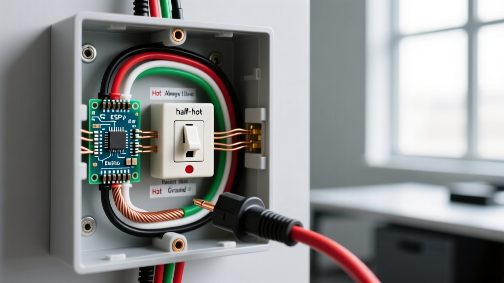

Understanding the 'Semi Plug' (Half-Hot Receptacle)
In residential and commercial electrical work, the colloquial term 'semi plug' refers to a semi-switched (or half-hot) receptacle. This is a standard duplex outlet where one half is controlled by a wall switch, while the other half remains constantly powered. When apprentices and DIYers search for a wiring diagram for semi plug configurations, they are usually trying to solve the puzzle of splitting the hot terminals to achieve this dual functionality.
This setup is incredibly common in living rooms and bedrooms where a switched lamp is desired, but a vacuum cleaner or router still needs constant power from the same wall box. As we navigate the 2026 NEC adoption cycle, understanding the precise terminal modifications and wire routing required for this setup is critical for both safety and code compliance.
⚠️ CRITICAL SAFETY WARNING: Always turn off the circuit breaker and verify the absence of voltage using a non-contact voltage tester (like the Klein Tools NCVT-4IR) before opening any junction box. Working on live 120V circuits poses a severe risk of arc flash and electrocution. For comprehensive safety protocols, refer to the Electrical Safety Foundation International (ESFI).
Anatomy of a Semi-Switched Receptacle
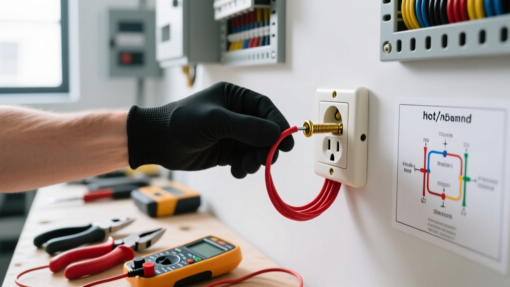
To create a semi plug, you must manipulate the physical brass connecting tab on the side of the receptacle. Standard duplex receptacles, such as the industry-standard Leviton T5262-E 15A Tamper-Resistant Receptacle, feature two brass (hot) terminals and two silver (neutral) terminals.
- The Brass Tab: Located on the hot side, this small metal bridge connects the top and bottom screws. This tab must be broken off using needle-nose pliers to isolate the top and bottom receptacles.
- The Silver Tab: Located on the neutral side. Never break this tab for a standard semi-switched setup. Both halves of the outlet must share the same neutral return path to prevent an open-neutral hazard and ensure proper breaker operation.
Scenario A: Power Source Enters at the Switch
This is the most straightforward wiring diagram for semi plug installations. Power from the breaker panel enters the switch box first, and a single cable runs from the switch to the receptacle.
Step-by-Step Execution
- At the Switch Box: Connect the incoming black (always-hot) wire to the bottom brass terminal of the single-pole switch. Connect the white wire of the 12/2 or 14/2 cable running to the receptacle to the top brass terminal of the switch. Pro Tip: Wrap black electrical tape around both ends of this white wire to re-identify it as a switched-hot conductor, per NEC Article 200.7.
- At the Receptacle Box: Connect the bare copper ground to the green grounding screw. Connect the white (neutral) wire to one of the silver terminals.
- Splitting the Hot: Connect the black (always-hot) wire to the bottom brass terminal. Connect the taped white wire (switched-hot) to the top brass terminal.
- Break the Tab: Snap off the brass fin between the top and bottom hot screws.
Scenario B: Power Source Enters at the Receptacle
This scenario is more complex and requires a 3-wire cable (e.g., 12/3 NM-B Romex) to carry both the always-hot and the switched-hot currents between the receptacle and the switch. If you only use 2-wire cable here, you will not have enough conductors to complete the circuit safely.
Step-by-Step Execution
- At the Receptacle Box: The incoming black (always-hot) wire is pigtailed with two wires: one goes to the bottom brass terminal (always-on half), and the other connects to the red wire of the 12/3 cable heading to the switch.
- The Switch Loop: The white wire of the 12/3 cable (re-identified with black tape) connects to the always-hot incoming black wire via a wire nut. This sends constant power down to the switch.
- At the Switch Box: The taped white wire connects to the bottom switch terminal. The red wire (switched return) connects to the top switch terminal.
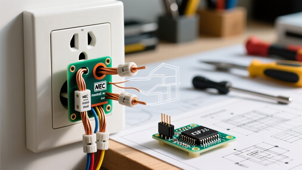
- Back at the Receptacle: The red wire from the 12/3 cable connects to the top brass terminal (switched half). Break the brass tab. Connect all neutrals (incoming white, 12/3 white if used as neutral, though in this loop the white is a hot) and grounds together with pigtails to the receptacle.
Wire Color Mapping & Terminal Matrix
The following table serves as a quick-reference wiring diagram for semi plug configurations based on Scenario A (Power at Switch).
| Wire Color / Type | Origin | Destination Terminal | Function |
|---|---|---|---|
| Bare Copper | Panel / Ground | Green Screw (Receptacle) | Equipment Grounding |
| White (Neutral) | Panel | Silver Screw (Receptacle) | Current Return Path |
| Black (Hot) | Panel to Switch | Bottom Brass Screw (Switch) | Always-Hot Feed |
| White (Taped Black) | Switch to Receptacle | Top Brass Screw (Receptacle) | Switched-Hot Feed |
| Black | Switch to Receptacle | Bottom Brass Screw (Receptacle) | Always-Hot Feed |
Common Failure Modes & Troubleshooting
Even experienced electricians make errors when configuring a semi-switched outlet. Below is a diagnostic matrix for common failure modes.
| Symptom | Probable Cause | Corrective Action |
|---|---|---|
| Both halves are always on; switch does nothing. | Failed to break the brass connecting tab on the receptacle. | Turn off power, remove receptacle, and snap the brass fin off completely. |
| Neither half works; breaker trips immediately. | Accidentally broke the silver (neutral) tab, or wired switched-hot to neutral. | Verify silver tab is intact. Check that black/red wires are ONLY on brass screws. |
| Switch works, but the 'always-on' half is dead. | Lost the always-hot pigtail connection at the wire nut or switch terminal. | Check continuity on the always-hot feed; ensure wire nuts are tight and no copper is exposed. |
| GFCI breaker trips when a lamp is turned on. | Neutral and ground are bonded downstream, or shared neutral on a GFCI circuit. | Ensure the semi-switched receptacle is on a standard AFCI breaker, not a dual-function GFCI, unless wired as a complete GFCI load. |
2026 NEC Code Compliance & Material Costs
When executing this wiring diagram, adherence to the NFPA NEC Code 70 is non-negotiable. Under the 2026 NEC adoption guidelines, all 15A and 20A receptacles in dwelling units must be Tamper-Resistant (TR). Furthermore, AFCI protection is required for almost all living spaces (Article 210.12). If you are installing a semi plug in a bedroom or living room, the circuit breaker must be an AFCI type.
Estimated Material Costs (2026 Pricing)
- 15A TR Duplex Receptacle (e.g., Leviton T5262): $1.85 - $2.50
- 12/2 NM-B Wire (per foot): $0.45 - $0.60
- 12/3 NM-B Wire (per foot, required for Scenario B): $0.75 - $0.95
- Single-Pole Toggle or Decora Switch: $1.50 - $4.00
- Ideal Wire-Nut Connectors (Tan/Red): $0.08 each
Frequently Asked Questions
Can I use a 14-gauge wire for a semi plug?
Yes, but only if the circuit is protected by a 15-amp breaker. If the breaker is 20-amp, NEC Article 240.4(D) strictly mandates the use of 12-gauge copper wire. Always match the wire gauge to the breaker rating and the receptacle's ampacity.
Do I need to break the tab on the neutral side?
No. Breaking the silver neutral tab is only done in very specific multi-wire branch circuit (MWBC) scenarios or when wiring two completely independent 120V circuits to a single yoke (which is generally prohibited in modern residential DIY without specific yoke-breaking receptacles). For a standard semi plug, the neutral tab must remain intact.
What happens if I wire the switched hot to the neutral terminal?
This will create a dead short the moment the wall switch is flipped to the 'ON' position. The breaker will trip violently, and you risk damaging the switch contacts or causing an arc flash. Always double-check that hot conductors (black, red, or taped white) terminate exclusively on brass screws.