
The Diagnostic Approach to Receptacle Anatomy
When a circuit fails, the receptacle is often the first point of investigation. However, simply swapping out a dead outlet without understanding the underlying failure mode is a recipe for recurring faults and potential fire hazards. To properly diagnose electrical issues, an electrician or advanced DIYer must understand the specific parts of electrical outlet assemblies and how they degrade over time. According to the National Fire Protection Association (NFPA), electrical distribution and lighting equipment are consistently among the leading causes of home fires, frequently stemming from high-resistance connections at the receptacle terminals.
In this 2026 diagnostic guide, we bypass basic definitions and focus on the forensic and functional aspects of receptacle components. We will examine how thermal cycling, mechanical fatigue, and improper installation compromise specific parts, and provide a structured workflow for pinpointing the exact point of failure using modern testing equipment like the Fluke 117 True-RMS multimeter and Klein Tools ET40 receptacle tester.
Core Components and Their Specific Failure Modes
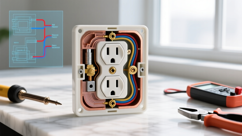
A standard NEMA 5-15R duplex receptacle consists of several critical sub-assemblies. Diagnosing a fault requires isolating which of these parts has failed.
1. The Yoke (Mounting Strap)
The yoke is the metal strap that secures the receptacle to the electrical box. In commercial-spec grade receptacles (like the Leviton 5262-SW), the yoke is constructed from heavy-duty steel designed to resist bending. In builder-grade models, the yoke is often thinner brass-plated steel.
- Diagnostic Indicator: If the outlet sits crooked in the wall or plugs insert at an angle, the yoke may be bent, or the plaster ears may be broken off. This misalignment causes uneven tension on the plug blades, leading to arcing.
- Failure Mode: Metal fatigue at the plaster ear score lines, often caused by over-tightening the mounting screws into a misaligned drywall cutout.
2. Terminal Systems: Side-Wire vs. Backstab (Push-In)
This is the most common source of residential electrical faults. The connection points where the copper wire meets the brass (hot) and silver (neutral) internal bus bars dictate the longevity of the circuit.
- Backstab (Push-In) Terminals: These rely on a beryllium copper spring to grip the wire. Over 10 to 15 years, thermal expansion and contraction cause this spring to lose tension. The resulting high-resistance connection generates heat, eventually melting the polycarbonate housing.
- Side-Wire (Screw) Terminals: The wire is looped around a brass or nickel-plated steel screw. When torqued correctly, this creates a gas-tight mechanical bond that rarely fails unless subjected to severe physical trauma or corrosive environments.
Expert Insight: The 2023 and upcoming NEC revisions continue to emphasize the reliability of terminal connections. If you are troubleshooting a dead outlet and find 14 AWG or 12 AWG wires pushed into the backstabs, the immediate diagnostic conclusion is spring fatigue until proven otherwise.
3. Internal Contact Wipers (The Slots)
The visible slots on the face of the receptacle are merely the entry points to the internal contact wipers. These wipers grip the male blades of the plug.
- Diagnostic Indicator: Use a UL-listed plug insertion/withdrawal tester. If a plug slides in with less than 3 ounces of pull force, the wipers have lost their mechanical memory (spring tension).
- Failure Mode: High-resistance arcing at the plug-to-wiper interface, which manifests as brown scorch marks on the face of the outlet or the plug itself.
4. The U-Ground and Grounding Path
The D-shaped slot is connected to the green grounding screw and the metal yoke. Its purpose is to provide a low-impedance fault path back to the panel to trip the breaker.
- Diagnostic Indicator: A reading of >0.5 ohms between the U-ground slot and a known good ground (like a copper water pipe or the panel ground bar) indicates a compromised grounding path, often due to paint on the yoke or a loose grounding screw.
Symptom-to-Component Failure Matrix
Use this diagnostic matrix to quickly narrow down which parts of the electrical outlet require inspection based on your initial field symptoms.
| Observed Symptom | Primary Suspect Component | Diagnostic Test / Tool | Likely Root Cause |
|---|---|---|---|
| Intermittent power when plug is wiggled | Internal Contact Wipers | Physical tension pull-test | Metal fatigue from repeated high-wattage appliance use |
| Outlet dead, but line side has 120V | Backstab Terminals / Brass Bus | Fluke 117 Voltage & Continuity Test | Beryllium spring failure (thermal cycling) |
| Buzzing or humming sound from wall | Terminal Screws / Wire Loop | FLIR Thermal Imaging (TiS60+) | Loose side-wire connection causing micro-arcing |
| Plugs insert crooked or fall out | Yoke / Faceplate Alignment | Visual inspection & level check | Bent yoke strap or broken plaster ears |
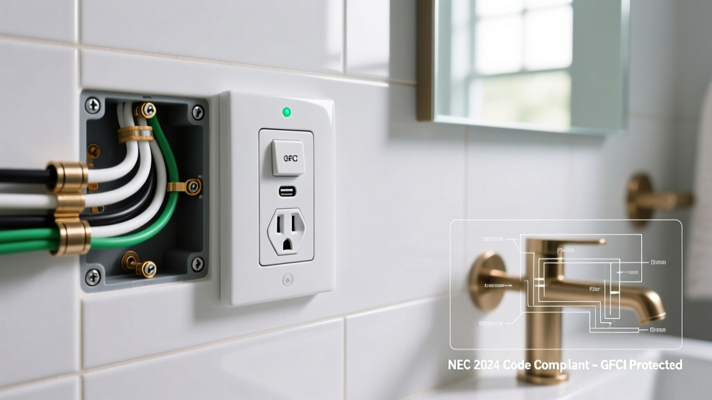
| GFCI trips immediately upon plugging in | Line/Load Reversal or Neutral Fault | Klein ET40 Receptacle Tester | Wired to LOAD side incorrectly or neutral-ground short |
Step-by-Step Diagnostic Workflow
When called to troubleshoot a failing receptacle, follow this sequential workflow to ensure safety and accuracy. The U.S. Consumer Product Safety Commission (CPSC) stresses that improper testing and handling of energized components remain a leading cause of DIY electrical injuries.
Step 1: Non-Intrusive Thermal Scan
Before removing the faceplate, scan the outlet with a thermal imager while a known load (like a 1500W space heater) is plugged in and running. Look for hot spots exceeding 120°F (49°C) on the face of the receptacle. A localized hot spot near the brass screw terminal indicates a high-resistance connection inside the housing.
Step 2: De-Energize and Verify
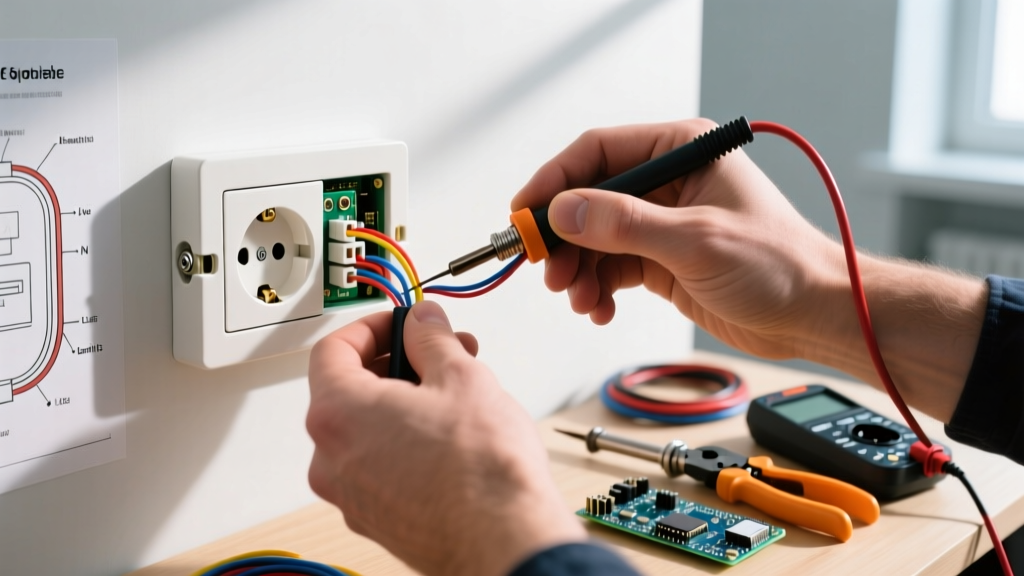
Turn off the circuit breaker. Use a non-contact voltage tester (NCVT), followed by a multimeter testing between Hot-to-Neutral, Hot-to-Ground, and Neutral-to-Ground to confirm 0.0V.
Step 3: The Yoke and Faceplate Inspection
Remove the faceplate. Inspect the thermoset plastic (typically urea-formaldehyde in commercial grades for high heat resistance) for micro-fractures. Check the yoke for bending. If the drywall cutout is uneven, the yoke will bow when the mounting screws are tightened, warping the internal bus bars.
Step 4: Terminal and Wiring Forensics
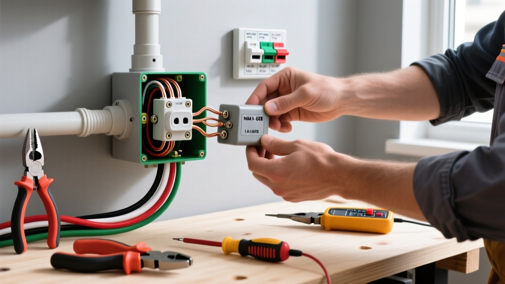
Extract the receptacle from the box. Examine the wiring method:
- If Backstabbed: Do not attempt to reuse the outlet. The internal springs are permanently deformed. Cut the wires back to fresh, un-oxidized copper, strip to 3/4 inch, and install a new commercial-spec grade receptacle using the side-wire screws or a screw-clamp mechanism.
- If Side-Wired: Check the wire loop. It should wrap clockwise around the screw, covering at least 270 degrees of the screw head. Ensure no bare copper is exposed outside the terminal pad, and no insulation is caught under the screw head, which acts as a dielectric barrier.
Step 5: Multi-Wire Branch Circuit (MWBC) Tab Check
If the outlet is fed by an MWBC (two hot wires sharing one neutral), the brass hot-side connecting tab must be broken off. If you find two different hot phases connected to an intact brass tab, you have diagnosed a catastrophic dead-short condition that should have tripped a 240V breaker. Use diagonal cutters to snap the brass fin before re-energizing.
Repair vs. Replace: 2026 Cost and Safety Analysis
Unlike mechanical switches, the internal parts of an electrical outlet cannot be disassembled and repaired. The diagnostic decision is always between re-terminating the wires on the existing device or replacing the device entirely.
The Builder-Grade Trap
Standard builder-grade receptacles (e.g., basic $1.50 models found in big-box bins) utilize thinner internal brass wipers and lower-grade thermoplastic housings. In 2026, with the increased continuous loads from modern electronics and smart home hubs, these units degrade rapidly. If your diagnostic testing reveals wiper fatigue or thermal deformation on a builder-grade unit, replacement is mandatory.
Upgrading to Commercial Spec-Grade
We strongly recommend upgrading to Commercial Specification Grade receptacles (such as the Leviton 5262 or Pass & Seymour 5266-X). Priced between $4.50 and $7.00 in 2026, these units feature:
- Thick, nickel-plated brass terminal screws for superior corrosion resistance.
- Polycarbonate or high-impact nylon faces that resist cracking and meet stringent UL94 V-0 flammability standards.
- Wrap-around yokes that prevent bowing and maintain precise slot alignment.
- Auto-ground clips that ensure a solid ground path to metal electrical boxes.
Frequently Asked Questions (FAQ)
Why is the neutral silver but the hot brass?
The National Electrical Code (NEC) mandates this color coding to ensure uniformity. The brass terminal connects to the ungrounded (hot) conductor, which carries the alternating current potential. The silver terminal connects to the grounded (neutral) conductor, which completes the circuit back to the transformer. Reversing these creates a shock hazard where the appliance's internal switch breaks the neutral, leaving the device energized even when turned off.
Can I use the backstab holes on a 20-Amp circuit?
No. Most 20-amp receptacles (NEMA 5-20R) do not even have backstab holes because the internal spring mechanisms cannot reliably handle the thermal expansion of 12 AWG wire under continuous 16-amp loads. Always use side-wiring or screw-clamp terminals for 20-amp circuits.
How do I test if the ground is actually connected?
While a simple $10 neon tester will light up to show a ground connection, it does not measure impedance. For a true diagnostic test, use a multimeter to measure voltage between Hot and Ground. It should read within 1-2 volts of the Hot-to-Neutral reading. A significantly lower voltage on the ground leg indicates a high-resistance ground fault somewhere upstream in the branch circuit.
For further reading on residential wiring safety standards and component requirements, refer to the U.S. Department of Energy's guide on home electrical system components. Understanding the precise anatomy and failure modes of these devices transforms troubleshooting from a guessing game into a precise, scientific discipline.