
The Complete Inspection & Testing Guide for 7-Way RV Blade Connectors
Tracing a faulty trailer lighting circuit is a rite of passage for any DIYer or fleet technician. While the standard 7-way RV blade connector (governed by the SAE J286 standard) is ubiquitous on everything from utility trailers to heavy fifth-wheels, it remains one of the most misunderstood electrical interfaces on the road. According to the Federal Motor Carrier Safety Administration (FMCSA), improper wiring and lighting failures account for a significant percentage of roadside vehicle out-of-service violations. In 2026, with modern tow vehicles utilizing complex PWM (Pulse Width Modulation) lighting controllers and multiplexed CAN-bus systems, guessing your way through a wiring diagram is no longer viable. This guide provides a rigorous, expert-level inspection and testing protocol to diagnose, verify, and repair your 7-blade trailer plug.
The Golden Rule: Pin Positions Over Wire Colors
The most common mistake DIYers make when referencing a wiring diagram for 7 blade trailer plug setups is trusting the wire insulation color. While the SAE J286 standard recommends specific colors, aftermarket harnesses, cheap replacement plugs (like generic imports found on online marketplaces), and older trailers frequently deviate from these norms. Pins are law; colors are merely suggestions. Always test and wire based on the physical pin position on the connector face, not the jacket color of the copper wire.
Standard SAE J286 Pinout Matrix
| Pin Position | Function | Standard Wire Color | Minimum AWG (Recommended) |
|---|---|---|---|
| 1 (Top / 12 o'clock) | Ground (Chassis) | White | 10 AWG |
| 2 (Top Right / 2 o'clock) | Tail / Running Lights | Brown | 12 AWG |
| 3 (Bottom Right / 4 o'clock) | Right Turn / Stop | Green | 12 AWG |
| 4 (Bottom / 6 o'clock) | Electric Brakes | Blue | 10 AWG |
| 5 (Bottom Left / 8 o'clock) | Left Turn / Stop | Yellow | 12 AWG |
| 6 (Top Left / 10 o'clock) | 12V Auxiliary / Battery Charge | Black or Red | 10 AWG |
| 7 (Center Pin) | Reverse Lights | Purple | 14 AWG |
Essential Inspection Toolkit for 2026
To properly test a 7-way connector, you must move beyond cheap continuity beepers. You need tools that can simulate loads and read precise voltage drops.
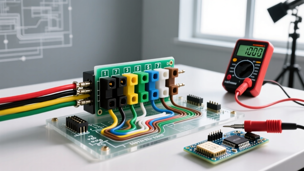
- Digital Multimeter (DMM): A True-RMS meter like the Fluke 117 ($180-$200) is essential for reading accurate DC voltage on modern truck PWM circuits. Refer to the official Fluke guide on testing voltage for proper DMM safety and setup.
- 7-Way Circuit Tester: The Hopkins 47995 ($15-$20) features integrated LEDs that simulate a basic load, instantly revealing dead pins or shorted circuits on the tow vehicle side.
- Dielectric Grease: Permatex 22058 ($8). Mandatory for packing the connector cavity to prevent copper oxide buildup (the green crust that causes high-resistance voltage drops).
- Heat Shrink & Crimpers: Use adhesive-lined marine-grade heat shrink (3M MDT) and a ratcheting crimping tool. Solder is brittle and will fracture under the constant vibration of a trailer tongue.
Phase 1: Tow Vehicle Source Testing (No Trailer Connected)
Before plugging in the trailer, you must verify that the tow vehicle is outputting the correct signals. Modern trucks (2020 and newer) often require a trailer to be plugged in to activate the tow module, which can complicate testing. If your truck requires a connected load, use a trailer emulator or have a helper sit in the cab while you test the trailer-side plug.
- Establish a Known Good Ground: Do not rely on the hitch ball. Hitch balls are often coated in grease, paint, or rust, creating high resistance. Clamp your multimeter's black lead directly to a bare, sanded metal spot on the truck's frame or the clean ground pin (Pin 1) of the truck-side receptacle.
- Test Running Lights (Pin 2): Turn on the truck's headlights. Probe Pin 2 with the red lead. You should read between 12.4V and 13.8V (with the engine running). If you read 8V-10V, you have a voltage drop issue in the truck's wiring harness or a corroded factory converter module.
- Test Turn Signals & Brakes (Pins 3 & 5): Activate the left turn signal. Probe Pin 5. On older trucks, you will see a steady pulsing between 0V and 13.5V. On newer trucks with PWM lighting, your True-RMS multimeter might read a fluctuating 9V-11V. This is normal; the truck is pulsing the power to save energy and reduce heat.
- Test Electric Brakes (Pin 4): Have a helper press the brake pedal or manually slide the in-cabin brake controller. Probe Pin 4. Voltage should scale from 0V up to 12V+ depending on the controller's gain setting.
- Test 12V Aux (Pin 6): Probe Pin 6. This should be a constant 12.4V - 13.8V, often tied to the truck's auxiliary relay which only powers up when the ignition is in the 'Run' position.
Phase 2: Trailer Side Continuity & Resistance Testing
Once the truck is verified, inspect the trailer's male plug and internal wiring. The Code of Federal Regulations (Title 49, Part 393, Subpart L) mandates strict visibility and lighting functionality, making robust trailer-side wiring a legal necessity, not just a convenience.
The Grounding Deep-Dive (Pin 1)
Over 80% of trailer lighting issues stem from a compromised ground. The white ground wire must be terminated with a heavy-duty ring terminal directly to the trailer's bare steel frame. Never ground the trailer solely through the hitch ball. The articulation of the hitch, combined with road grime and dielectric grease, creates a variable resistor.
Expert Test: Set your multimeter to Ohms (Ω). Place one probe on the ground pin of the trailer plug, and the other on the metal housing of the furthest tail light. The resistance should read less than 0.5 Ω. If it reads higher, the white wire is undersized, corroded, or the frame ground point is rusted.
Advanced Edge Cases & Modern Troubleshooting
LED Upgrades and PWM Controller Faults
If you have upgraded your trailer from incandescent bulbs to LED assemblies, you may encounter 'hyper-flashing' or the tow vehicle's dashboard throwing a 'Trailer Wiring Fault' code. Incandescent bulbs draw roughly 2.1 Amps each, while LEDs draw less than 0.3 Amps. Modern truck body control modules (BCMs) monitor current draw; if the draw is too low, the BCM assumes a bulb is blown and cuts the circuit.
The Fix: Install active load resistors (such as the Curt 57003 or inline PWM emulators) on the yellow and green turn signal circuits to simulate the 2.1A draw of a traditional 1157 bulb. Do not use cheap ceramic wire-wound resistors that generate massive heat; opt for modern active electronic emulators designed for CAN-bus systems.
Voltage Drop on Long Trailers
For trailers exceeding 25 feet, running 12 AWG wire for the 12V auxiliary or electric brake circuits will result in severe voltage drop. By the time 13.2V leaves the truck, it may arrive at the trailer's breakaway battery or brake magnets at a sluggish 9.5V, resulting in weak braking performance.
The Fix: Always upsize the Blue (Brakes), Black (Aux), and White (Ground) wires to 10 AWG or 8 AWG for trailers over 25 feet. Use the voltage drop formula: V_D = (2 x K x I x L) / CM to calculate exact losses over your specific cable run.
Troubleshooting Matrix: Symptoms to Solutions
| Symptom | Multimeter Reading | Probable Root Cause | Expert Fix |
|---|---|---|---|
| Turn signals flash rapidly on dash | Normal Voltage, Low Amperage | LED upgrade without load emulation | Install CAN-bus active load resistors on turn circuits. |
| Running lights dim when brakes applied | Voltage drops from 13V to 9V on Brown wire | Shared ground path overloading / Ground loop | Run dedicated 10 AWG ground wire; clean frame contact points. |
| Electric brakes feel weak or pulse erratically | 8.5V at Pin 4 (Trailer side) under load | Undersized wire (12 AWG) causing voltage drop | Rewire Blue brake circuit with 10 AWG copper; check magnets. |
| Blown truck fuse when plugging in trailer | 0 Ω (Dead Short) between Pin 6 and Ground | Pinched 12V Aux wire near the tongue jack | Inspect tongue pivot area; repair with adhesive marine heat shrink. |
Final Assembly and Weatherproofing
Once testing is complete and all circuits verify within specification, the final step is environmental sealing. Pack the interior cavity of both the male and female 7-way connectors with Permatex 22058 Dielectric Grease. This displaces moisture and prevents the galvanic corrosion that occurs when dissimilar metals (like brass pins and copper wire) are exposed to road salt and humidity. Ensure the rubber weather boot is pulled fully over the cable jacket, and secure it with a UV-resistant zip tie or stainless steel hose clamp to prevent water from wicking up inside the wire insulation via capillary action.
By relying on pin positions rather than wire colors, utilizing a True-RMS multimeter, and addressing the physical realities of grounding and voltage drop, you can ensure your 7-blade trailer plug operates flawlessly, keeping you safe and compliant on the road.