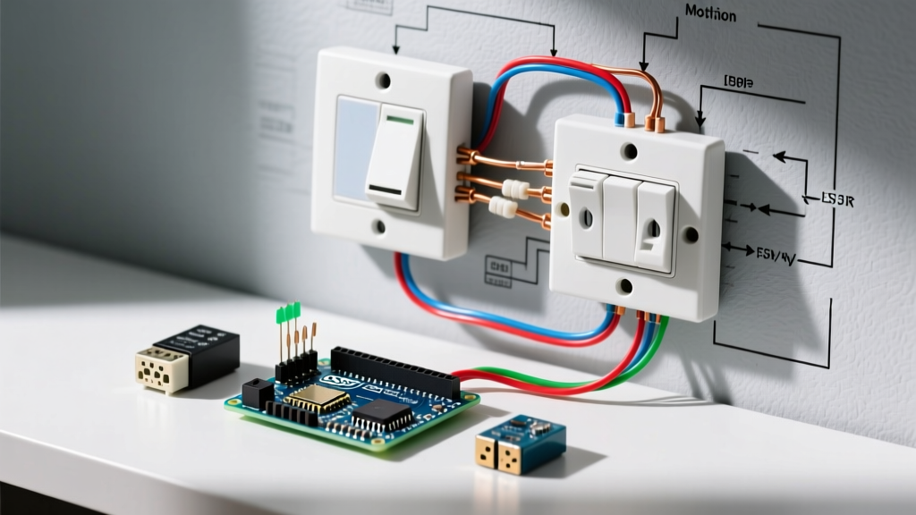

Decoding the Standard Wiring Diagram for Motion Sensor Light Switches
Upgrading to automated lighting is one of the most effective ways to reduce residential energy consumption. According to the U.S. Department of Energy, integrating occupancy sensors can reduce lighting energy waste by up to 68% in high-traffic transitional spaces like hallways, garages, and laundry rooms. However, the transition from a standard toggle switch to an active electronic sensor introduces new wiring complexities. Understanding the correct wiring diagram for motion sensor light switch configurations is critical to avoiding blown internal relays, ghost-switching, and potential fire hazards.
Unlike a simple mechanical single-pole switch that merely interrupts the hot wire, a motion sensor requires continuous power to operate its internal Passive Infrared (PIR) or ultrasonic microprocessors. This means the wiring diagram will almost always involve four distinct connections: Line (Hot), Load, Neutral, and Ground. In 2026, the vast majority of modern LED-compatible sensors—such as the Leviton PR180 and Lutron MS-OPS2—rely on a dedicated neutral wire to complete the 120V circuit for the sensor's internal logic board, independent of the lighting load.
Anatomy of the Sensor Wiring Harness
Before tackling any specific scenario, you must identify the wires in both your wall box and the sensor's pigtail harness. While manufacturer color codes can vary slightly, the industry standard for 120V residential motion sensors follows this pattern:
- Black (or Red) Wire: Line / Hot (Connects to the always-on power source from the breaker panel).
- Blue (or Red with White Stripe) Wire: Load (Connects to the switched hot wire leading to the light fixture).
- White Wire: Neutral (Connects to the bundle of white neutral wires in the back of the box).
- Green (or Bare Copper) Wire: Ground (Connects to the bare copper ground bundle and the metal box, if applicable).
Scenario 1: The Standard Single-Pole Configuration
The single-pole setup is the most common residential scenario, controlling a light fixture from a single wall box. Here is the step-by-step execution based on the standard single-pole wiring diagram:
- Verify Power: Turn off the breaker and verify zero voltage using a non-contact voltage tester (e.g., Klein NCVT-2) and a multimeter at the switch terminals.
- Identify Line vs. Load: In a single-pole box, you will typically see one black wire bringing power in (Line) and one black wire taking power to the light (Load). If both wires are black and unlabeled, you must temporarily restore power and use a voltage tester to identify which wire is 'always hot' (Line). Mark it with black electrical tape.
- Connect Ground: Connect the sensor's green wire to the bare copper ground bundle using a Wago 221 lever nut or an Ideal 33 wire nut.
- Connect Neutral: Connect the sensor's white wire to the existing bundle of white neutral wires in the back of the box. Do not connect the sensor's white wire to the bare ground wire.
- Connect Line and Load: Connect the sensor's black (Line) wire to your identified always-hot wire. Connect the sensor's blue or red (Load) wire to the wire leading to the fixture.
Scenario 2: The 3-Way Motion Sensor Diagram
Wiring a motion sensor in a 3-way scenario (controlling one light from two locations) is notoriously complex because standard 3-way switches use 'traveler' wires, which motion sensors cannot interpret. You have two primary diagram paths for this scenario:
Path A: Dual-Sensor Setup (No Travelers)
Advanced models like the Lutron MS-OPS2 allow you to wire two motion sensors in a 3-way configuration without using traditional traveler wires. The wiring diagram for this requires wiring both sensors as single-pole devices in their respective boxes, connecting the Load wires from both sensors together via the 3-way traveler wire to the light fixture. This creates a parallel logic circuit where either sensor can trigger the load.
Path B: Master Sensor + Companion Switch
Alternatively, you can wire one 'Master' motion sensor and one standard mechanical 'Companion' switch. The master sensor handles the neutral and load connections, while the companion switch simply acts as a manual override to interrupt the Line voltage before it reaches the master sensor. Always consult the manufacturer's specific 3-way diagram, as miswiring the travelers into a sensor's Load terminal will instantly destroy the internal triac.
Scenario 3: Navigating 'No Neutral' Wiring Diagrams
Homes built before 1985 often lack a neutral wire in the switch box, a reality that conflicts with the National Electrical Code (NEC) Article 404.2(C), which now mandates neutral wires at virtually all switch locations for future smart home compatibility. If you are retrofitting an older home and your box lacks a white neutral bundle, you must use a 'No-Neutral' motion sensor.
No-neutral sensors (like the Lutron MS-OPS2H) operate by allowing a micro-current (leakage current) to pass through the light fixture itself to complete the sensor's internal circuit. When reading the wiring diagram for a no-neutral sensor, you will notice the white wire is capped off and unused. However, this creates a specific edge case:
Expert Warning: If your lighting load is too low (typically under 20 watts of LED), the micro-current will cause the LEDs to flicker or glow when the switch is off. To resolve this, you must wire a Minimum Load Compensator (such as the Lutron LUT-MLC, costing around $12) in parallel across the light fixture at the ceiling canopy, not at the switch box.
2026 Motion Sensor Switch Specification Matrix
Selecting the right hardware dictates which wiring diagram you will follow. Below is a comparison of top-tier residential motion sensors available in 2026:
| Brand & Model | Neutral Required? | Max LED Load | Avg. Price (2026) | Best Use Case |
|---|---|---|---|---|
| Lutron MS-OPS2 | Optional | 150W / 2.5A | $42 - $48 | Older homes, dual-sensor 3-way |
| Leviton PR180-1LW | Yes | 150W LED / 800W Incandescent | $35 - $40 | Standard new-construction single-pole |
| Eaton DSD602 | Yes | 150W LED | $38 - $45 | High-traffic commercial/office |
| TopGreener TSOS5 | Yes | 150W LED / 600W Incandescent | $25 - $30 | Budget retrofits with deep boxes |
The Hidden Constraint: Box Fill Calculations
A critical mistake DIYers make when following a wiring diagram is ignoring the physical depth of the sensor. Motion sensor switches are exceptionally deep—often protruding 1.5 to 1.75 inches into the wall cavity due to the relay and PIR lens housing.
Under NEC Article 314.16, you must calculate box fill. A standard 14-cubic-inch single-gang box is almost never sufficient for a motion sensor, the wire nuts, and the incoming 14/2 or 12/2 Romex cables. Actionable Advice: Before purchasing your sensor, measure your existing wall box. If it is a standard shallow box, budget an extra $45 to $60 to hire an electrician (or DIY if permitted) to swap it for a 22.5-cubic-inch 'deep' old-work box. Forcing a deep sensor into a shallow box will pinch the neutral wires against the back of the device, leading to arcing and melted wire insulation over time.
Troubleshooting Edge Cases and Ghost Switching
Even with a perfect wiring diagram execution, environmental factors can cause operational failures.
- Ghost Switching (Turning on with no motion): Often caused by HVAC registers blowing hot or cold air directly into the PIR sensor's field of view. PIR sensors detect changes in infrared heat signatures. A blast of 72°F air across a 65°F wall will trigger the relay. Adjust the sensor's physical mask or relocate the HVAC deflector.
- Failure to Turn Off (Timeout Ignored): If the light stays on indefinitely, the sensor may be detecting 'micro-motion' from ceiling fans, hanging plants, or pets. Switch the sensor from PIR-only to Dual-Technology (PIR + Ultrasonic) if the room has high ceilings, or manually dial back the sensitivity potentiometer located behind the faceplate.
- LED Flickering on Startup: Caused by incompatible LED drivers. Ensure your bulbs are marked 'Dimmable' or 'Sensor Compatible'. In 2026, look for LEDs with built-in surge protection rated for at least 2kV, as the mechanical relay inside the sensor can create micro-spikes upon engagement.
By meticulously matching your wall box's existing wiring to the correct manufacturer diagram, respecting box fill limits, and understanding the nuances of neutral vs. no-neutral current leakage, you can achieve a flawless, code-compliant motion sensor installation that will operate reliably for years.