
The Critical Role of Kitchen Receptacle Testing
The modern kitchen is the most electrically demanding environment in any residential or commercial property. Between high-wattage countertop appliances, continuous moisture exposure, and strict code requirements, a faulty kitchen electrical outlet is a primary catalyst for electrical fires and severe shock hazards. As of 2026, home inspectors and master electricians rely on rigorous, multi-stage diagnostic protocols rather than simple visual checks to verify safety and compliance.
This comprehensive inspection and testing guide details the exact procedures, professional-grade tools, and National Electrical Code (NEC) benchmarks required to thoroughly evaluate every kitchen electrical outlet. Whether you are auditing an existing installation or verifying new construction, this protocol ensures absolute safety and operational integrity.
Phase 1: Visual and Physical Inspection Protocol
Before introducing any testing equipment, a meticulous physical examination of the receptacle and surrounding enclosure is mandatory. This phase identifies mechanical failures and code violations that electronic testers cannot detect.
Tamper-Resistant (TR) and Weather-Resistant (WR) Verification
Under NEC 406.12, all 15A and 20A, 125V and 250V non-locking receptacles in kitchens must be Tamper-Resistant (TR). Inspect the face of the outlet for the stamped "TR" designation. Physically test the internal shutters using a TR tester or a non-conductive probe; both shutters must open simultaneously when equal pressure is applied. If a single slot accepts a probe while the other remains blocked, the internal spring mechanism has failed, and the receptacle must be replaced immediately.
For outlets located within 6 feet of a sink or in wet locations, verify the presence of a Weather-Resistant (WR) receptacle (marked with "WR") paired with an extra-duty, in-use bubble cover. Standard indoor receptacles degrade rapidly in high-humidity kitchen zones, leading to internal corrosion and increased resistance.
Phase 2: Circuit Mapping and NEC Compliance
A compliant kitchen requires dedicated Small Appliance Branch Circuits (SABCs). According to the National Fire Protection Association (NFPA) and NEC 210.52(B), a minimum of two 20-ampere small-appliance branch circuits must be provided to serve all countertop receptacles. These circuits cannot supply lighting, range hoods, or built-in appliances.
Mapping the SABCs
Use a circuit tracer (such as the Klein Tools ET910) to map every kitchen electrical outlet to its corresponding breaker. Verify the following parameters:
- Breaker Rating: Must be 20A (no 15A breakers permitted for countertop SABCs).
- Wire Gauge: Must be 12 AWG copper minimum.
- Receptacle Rating: 15A or 20A duplex receptacles are permitted on a 20A circuit, provided there is more than one outlet on the yoke.
| Parameter | Minimum Requirement | Common Violation |
|---|---|---|
| Number of Circuits | Two (2) dedicated 20A circuits | Sharing a circuit with kitchen lighting |
| Conductor Size | 12 AWG Copper | Using 14 AWG on a 20A breaker |
| GFCI Protection | Required for all countertop outlets | Missing GFCI near the sink zone |
| AFCI Protection | Required at the breaker panel | Using standard thermal-magnetic breakers |
Phase 3: Advanced GFCI and Ground Fault Testing
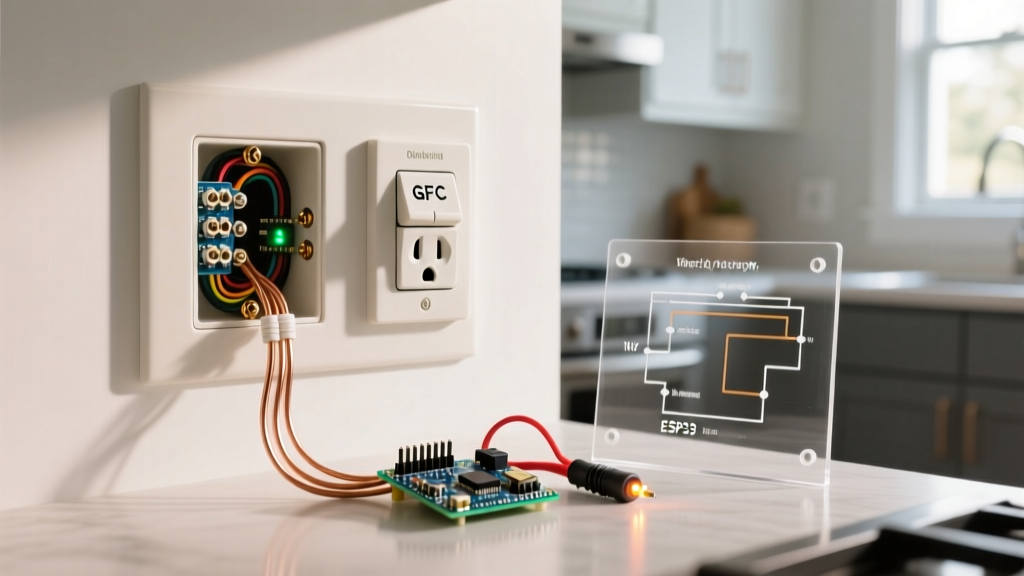
NEC 210.8(A)(6) mandates Ground-Fault Circuit-Interrupter (GFCI) protection for all kitchen electrical outlets serving countertops. However, verifying GFCI functionality requires more than pressing the built-in test button.
The "Test Button" Fallacy vs. Solenoid Testing
Pressing the "TEST" button on a GFCI receptacle only verifies that the internal electronic sensing circuit and the trip relay are functional. It does not verify the integrity of the equipment grounding conductor (EGC). If the outlet is ungrounded, the test button will still trip the device, giving a false sense of security.
To perform a true ground-fault test, use a solenoid-based GFCI tester like the Klein Tools RT250 (approx. $35). This device creates an actual current leakage between the hot and ground terminals. If the ground path is broken or has high impedance, the GFCI will not trip when the tester is activated. According to the Electrical Safety Foundation International (ESFI), regular functional testing of GFCIs is critical to preventing fatal electrocution in wet environments.
Expert Diagnostic Threshold: A compliant Class A GFCI must trip when the ground-fault current reaches between 4 and 6 milliamps (mA). If your digital GFCI analyzer (such as the Ideal SureTest 61-036) registers a trip at 8mA or higher, the internal sensing toroid is degrading and the receptacle must be replaced, even if the mechanical button still works.
Phase 4: Load Testing and Thermal Diagnostics
Kitchen outlets routinely handle continuous loads from appliances like coffee makers, toasters, and microwaves, often drawing 12A to 15A simultaneously. This phase tests the physical integrity of the wiring terminations under real-world stress.
Voltage Drop Under Heavy Appliance Load
Connect a 1500W resistive load (such as a space heater or high-wattage microwave) to the kitchen electrical outlet. Using a True-RMS digital multimeter (e.g., Fluke 117, approx. $200), measure the voltage at the receptacle before and during the load.
According to NEC informational notes, branch circuit voltage drop should not exceed 3%. On a nominal 120V circuit, the voltage under full load should not drop below 116.4V. A drop below this threshold indicates undersized wiring, excessively long circuit runs, or high-resistance connections at the breaker or splices.
Thermal Imaging for Termination Failures
While the 1500W load is running, scan the receptacle faceplate and the surrounding wall with a thermal imaging camera (e.g., Fluke TiS20+). Look for thermal anomalies. A temperature rise of more than 10°C (18°F) above ambient room temperature at the terminal screws indicates a failing connection.
Failure Mode Alert: "Backstabbed" (push-in) terminal connections are notorious for loosening under thermal cycling. If thermal imaging reveals a hot spot on a backstabbed 12 AWG wire, the receptacle must be replaced, and the wires must be terminated using the side-binding screw terminals or a proper pigtail wire nut connection.
Phase 5: Edge Cases and Multi-Wire Branch Circuits (MWBC)
In many larger kitchens, electricians utilize Multi-Wire Branch Circuits (MWBC) to supply the two required SABCs using a single 12/3 NM-B cable (sharing a neutral). This presents unique testing challenges.
- Handle Ties and Common Trip: NEC 210.4(B) requires a simultaneous disconnect for all ungrounded conductors. Verify that the two 20A breakers are secured with an identified handle tie or are a single 2-pole breaker.
- AFCI Nuisance Tripping: As of the 2023/2026 NEC cycles, AFCI protection is required in kitchens. If an MWBC is wired to two separate single-pole AFCI breakers instead of a single 2-pole AFCI breaker, the shared neutral will cause an immediate imbalance, resulting in continuous nuisance tripping. If a kitchen electrical outlet on an MWBC trips the AFCI immediately upon plugging in a device, verify the breaker configuration at the panel.
Troubleshooting Matrix: Common Kitchen Outlet Failures
Use this diagnostic matrix to quickly identify and resolve the most frequent issues encountered during kitchen electrical outlet inspections.
| Symptom | Diagnostic Test | Probable Cause & Solution |
|---|---|---|
| GFCI trips immediately when appliance is plugged in | Test appliance on a known non-GFCI circuit; check for neutral-ground fault. | Appliance has an internal ground fault, or the neutral and ground are bonded downstream. Isolate the fault. |
| Outlet shows "Open Ground" on a 3-light tester | Verify ground at the panel; check for broken EGC in the wall cavity. | Missing or disconnected bare copper ground wire. Re-terminate the ground pigtail at the receptacle grounding screw. |
| Receptacle faceplate feels warm to the touch | Thermal scan under 15A load; check terminal screw torque. | Backstabbed connections or loose side-screws. Replace receptacle (e.g., Leviton GFTN1-W, ~$22) and use screw terminals. |
| Hot/Neutral Reverse indicated | Visual inspection of brass (hot) and silver (neutral) screws. | Black wire landed on silver screw. Swap wires to correct polarity; this is a severe shock hazard. |
Final Verification and Documentation
A professional kitchen electrical outlet inspection is incomplete without proper documentation. Record the trip times (in milliseconds) and trip currents (in mA) for every GFCI device tested. Note the voltage drop measurements under load and map the final circuit directory at the breaker panel. For further safety guidelines regarding kitchen electrical environments, always consult the latest resources from the U.S. Consumer Product Safety Commission (CPSC).
By adhering to this rigorous testing protocol, you ensure that the kitchen's electrical infrastructure can safely handle the demands of modern appliances while providing uncompromising protection against ground faults and thermal failures.