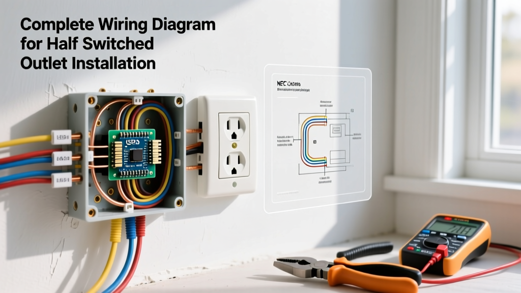

Understanding the Wiring Diagram for Half Switched Outlet Setups
A half-switched outlet, commonly known as a split receptacle, is a staple in modern residential wiring. It allows one half of a standard duplex receptacle to remain constantly hot (always on) while the other half is controlled by a wall switch. This configuration is heavily utilized in living rooms and bedrooms, providing permanent power for clocks, routers, or air purifiers, while offering switched control for floor lamps or accent lighting. Mastering the wiring diagram for half switched outlet installations requires a firm grasp of terminal anatomy, switch loop mechanics, and current National Electrical Code (NEC) requirements.
In this comprehensive 2026 guide, we will break down the exact wiring schematic, detail the physical installation steps, and highlight the critical failure modes that cause tripped breakers and dead circuits. Whether you are upgrading an older home or running new construction, this step-by-step installation guide ensures a safe, code-compliant result.
CRITICAL SAFETY WARNING: Always verify power is off at the main service panel using a non-contact voltage tester before opening any junction box. According to the Electrical Safety Foundation International (ESFI), electrical fires and shocks remain a leading cause of residential injuries. Never work on live circuits. If you are unfamiliar with local codes, consult a licensed electrician.
Tools and Materials Required
Using professional-grade tools ensures clean wire stripping, secure terminations, and long-term reliability. Below is the recommended bill of materials for a standard 15-amp residential split receptacle installation.
| Item Category | Recommended Product / Model | Estimated Cost (2026) | Purpose |
|---|---|---|---|
| Receptacle | Leviton 5320-W (15A Duplex TR) | $1.80 - $2.50 | Tamper-resistant split outlet |
| Wire (Feed & Loop) | Southwire 14/2 or 12/2 NM-B | $0.65 / ft | Power feed and switch loop |
| Wire Strippers | Klein Tools 11057 (10-18 AWG) | $26.00 | Precision insulation removal |
| Voltage Tester | Fluke 2AC-II VoltAlert | $38.00 | Live circuit verification |
| Connectors | WAGO 221 Lever Nuts (3 & 5 port) | $0.60 / ea | Secure, push-in pigtailing |
| Torque Screwdriver | Klein Tools 32500 (if required) | $45.00 | Terminal torque verification |
Anatomy of the Split Receptacle Diagram
To successfully interpret any wiring diagram for half switched outlet configurations, you must understand the physical breakaway tabs on the sides of the receptacle. A standard duplex outlet features two brass (hot) screws and two silver (neutral) screws, connected by metal fins (tabs) on the strap.
The Brass Tab (Hot Side)
For a half-switched setup, the brass tab must be removed. This physically separates the top and bottom hot terminals. The bottom brass screw will receive continuous line voltage, while the top brass screw will receive the switched hot return from the wall switch.
The Silver Tab (Neutral Side)
Leave the silver tab intact for standard 2-wire switch loop installations. Both the top and bottom receptacles share the same neutral return path. Exception: If you are wiring a Multi-Wire Branch Circuit (MWBC) utilizing a 14/3 or 12/3 cable with two separate hot legs sharing a single neutral, you must break the silver tab as well to prevent a dead short across the 240V phases (NEC Article 210.4).
Step-by-Step Installation Guide
Step 1: Power Verification and Box Preparation
Turn off the breaker controlling the room. Use your Fluke VoltAlert to test the existing outlet. Once dead, remove the faceplate and unscrew the receptacle. Pull the device out of the box to inspect the wiring. Per NFPA NEC Article 300.14, you must maintain at least 6 inches of free conductor length measured from the point where the wires enter the box. If the wires are too short, you must extend them using WAGO lever nuts and pigtails.
Step 2: Break the Brass Breakaway Tab
Take your new Leviton 15A TR receptacle. Using a pair of needle-nose pliers, grip the small brass metal fin located between the top and bottom brass screws. Bend it back and forth until it snaps cleanly off. Pro Tip: Ensure the broken tab does not fold back and touch the metal mounting strap of the receptacle, as this will cause an immediate ground fault or short circuit when the device is pushed into a metal box.
Step 3: Wire the Wall Switch (Single Pole)
At the switch box, you will typically find a 14/2 or 12/2 cable acting as the "switch loop."
- Connect the incoming continuous hot (black wire from the panel) to the bottom terminal of the single-pole switch.
- Connect the white wire of the switch loop to the top terminal of the switch. Code Requirement: Per NEC Article 200.7(C)(2), this white wire is being used as a hot supply to the switch and must be re-identified with black electrical tape or heat shrink at both ends.
- Connect all bare copper ground wires together with a wire nut or WAGO nut, and pigtail to the switch's green ground screw.
Step 4: Terminate the Receptacle
Back at the outlet box, route the wires to the newly tab-broken receptacle:
- Continuous Hot: Connect the main black feed wire from the panel to the bottom brass screw.
- Switched Hot Return: Connect the white wire (with black tape) coming back from the wall switch to the top brass screw.
- Neutral: Connect the white neutral wire from the panel to one of the silver screws. (If daisy-chaining to another outlet, use a WAGO 3-port lever nut to pigtail the neutral).
- Ground: Connect the bare copper wire to the green grounding screw at the bottom of the receptacle.
Step 5: Box Fill and Device Mounting
Carefully fold the wires into the back of the junction box. Push the grounds to the very back, followed by the neutrals, and finally the hots. Mount the receptacle using the provided 6-32 machine screws. Ensure the device is plumb and the plaster ears are flush against the drywall or junction box edge.
Step 6: Final Testing
Restore power at the breaker. Plug a receptacle tester or a simple lamp into the bottom half—it should turn on immediately. Plug the lamp into the top half—it should only turn on when the wall switch is toggled. If the breaker trips immediately, shut it off and revisit the troubleshooting matrix below.
Troubleshooting Matrix: Common Failure Modes
Even with a perfect wiring diagram for half switched outlet setups in mind, physical execution errors occur. Use this matrix to diagnose issues.
| Symptom | Root Cause | Corrective Action |
|---|---|---|
| Both top and bottom outlets turn on/off with the wall switch. | The brass breakaway tab was not removed, linking the continuous hot and switched hot together. | Turn off power, remove receptacle, and snap off the brass tab. |
| Breaker trips instantly upon restoring power. | The switch loop white wire (re-identified hot) was accidentally tied to the neutral bus or silver screw, creating a direct dead short. | Verify the taped white wire is strictly on the brass (top) screw and isolated from all white neutrals. |
| Switched half is dead, but continuous half works. | Switch is wired incorrectly, or the black tape was omitted and the white wire was spliced with neutrals in the switch box. | Check switch box. Ensure the taped white wire goes to the switch terminal, not a neutral wire nut. |
| Receptacle feels warm to the touch under load. | Loose terminal screws or back-stabbed push-in connections causing high resistance. | Always use the side-screw terminals and wrap the wire clockwise. Torque to manufacturer specs (usually 14 in-lbs). |
Frequently Asked Questions
Can I use a dimmer switch on a half-switched outlet?
Yes, but with strict limitations. You can install a smart dimmer or standard dimmer (like the Lutron Maestro MACL-153M) to control the top half of the outlet if it is dedicated to dimmable LED floor lamps. However, you must ensure the dimmer is rated for receptacle loads, not just hardwired lighting fixtures. Furthermore, standard dimmers require a neutral wire; if your switch box only has a 2-wire switch loop, you will need to either pull a neutral or use a specialized no-neutral dimmer, which may cause LED flickering.
Does the NEC require Tamper-Resistant (TR) receptacles for split outlets?
Yes. Under NEC Article 406.4(F), all 15A and 20A, 125V and 250V nonlocking receptacles installed in dwelling units must be listed as Tamper-Resistant. This applies to split receptacles just as it does to standard ones. The internal shutters prevent children from inserting foreign objects into the slots.
What if my box only has one 14/2 cable and no switch loop?
If you only have one 14/2 cable (one hot, one neutral, one ground) entering the outlet box, you cannot create a half-switched outlet without pulling new wire. You must run a new 14/2 cable from the outlet box to the desired switch location to create the switch loop described in Step 3.