
Why Upgrade Your Electrical Outlets in 2026?
The modern home demands more from its electrical infrastructure than ever before. Whether you are integrating high-draw smart home hubs, installing built-in USB-C PD (Power Delivery) receptacles, or upgrading to AFCI/GFCI protection to meet the latest 2023 and 2026 National Electrical Code (NEC) standards, the first physical step is always the same: you must safely extract the old hardware. Knowing how to properly remove electrical outlet components without damaging the surrounding drywall, junction box, or wiring is a foundational skill for any DIY upgrade or replacement project.
Upgrading a standard 15-amp duplex receptacle to a 20-amp commercial-grade model (like the Leviton T5262) or a tamper-resistant GFCI (like the Eaton GFTR15) requires careful extraction, wire inspection, and box-fill assessment. This guide provides an expert-level, step-by-step methodology to remove your existing receptacle and prepare the junction box for your new upgrade.
Essential Tool Matrix for Outlet Removal
Using the correct tools prevents stripped screws, damaged wire insulation, and accidental shorts. Below is the recommended 2026 toolkit for residential receptacle replacement.
| Tool Category | Recommended Model | Approx. 2026 Cost | Specific Purpose |
|---|---|---|---|
| Voltage Tester | Fluke T+PRO | $135.00 | Verifies absence of AC/DC voltage and tests GFCI tripping. |
| Wire Strippers | Klein Tools 11055 | $29.00 | Strips 14-24 AWG without nicking the copper conductor. |
| Utility Knife | Milwaukee Fastback 48-22-1901 | $15.00 | Scores painted-over faceplates to prevent drywall tear-out. |
| Screwdriver | Wiha 320P8 Slotted/Phillips | $22.00 | Insulated 1000V rated for terminal screw removal. |
| Needle-Nose Pliers | Knipex 110mm ESD | $38.00 | Forms precise J-hooks on 12 AWG and 14 AWG solid copper wire. |
Step-by-Step Guide: How to Remove Electrical Outlet Safely
Follow this precise sequence to ensure safety and preserve the integrity of your wall box and conductors.
Step 1: Kill the Power and Verify (LOTO Protocol)
Never rely solely on a wall switch or a non-contact voltage pen to confirm a dead circuit. Non-contact testers can yield false negatives due to capacitive coupling or shielded cables.
- Locate your main electrical panel and switch the corresponding breaker to the OFF position.
- Apply a residential Lockout/Tagout (LOTO) device to the breaker to prevent accidental re-engagement by other household members.
- Remove the faceplate screws and carefully pull the receptacle outward slightly.
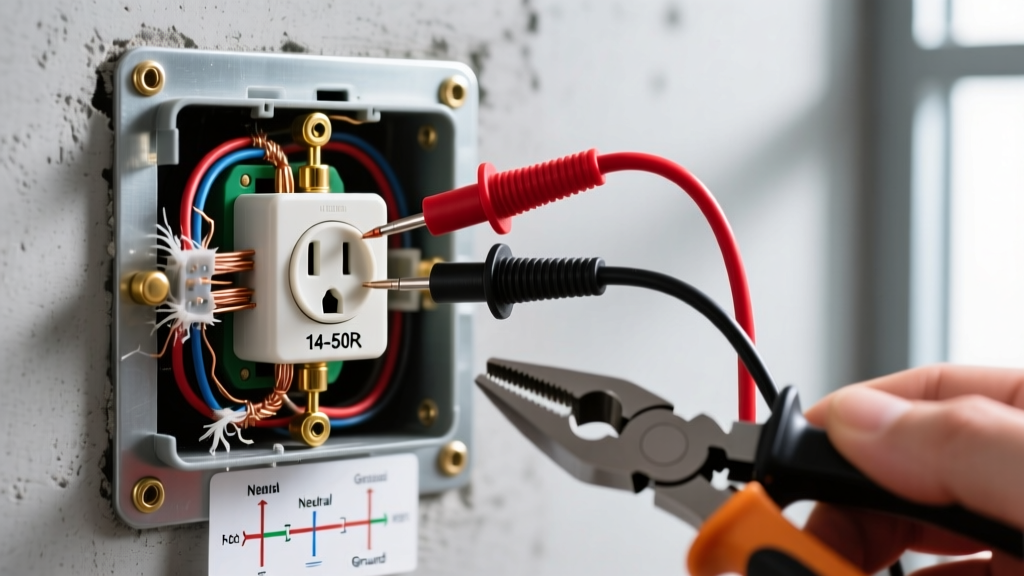
- Use a contact voltage tester (like the Fluke T+PRO) to test between the hot (brass) terminal and the neutral (silver) terminal, then between the hot terminal and the ground (green) screw. The reading must be exactly 0.0V.
Safety Warning: According to the National Fire Protection Association (NFPA), working on energized circuits is the leading cause of residential arc flash incidents. Always verify zero energy before touching bare copper or terminal screws.
Step 2: Score the Paint and Remove the Yoke
In older homes, or even in newer builds that have been repainted, latex paint often seals the gap between the faceplate and the wall. Ripping the plate off will tear the drywall paper facing.
- Take your utility knife and lightly score the perimeter of the faceplate where it meets the wall.
- Remove the top and bottom 6-32 machine screws securing the receptacle yoke (the metal mounting strap) to the junction box.
- Gently pull the receptacle out of the box. If it resists, do not yank the wires. Instead, grip the metal yoke with your pliers and gently rock it side-to-side to break the paint seal against the drywall.
Step 3: Disconnect the Wiring (Side-Wired vs. Backstabbed)
How you remove the wires depends entirely on how the original electrician terminated them.
Scenario A: Side-Wired (Screw Terminals)
This is the preferred, code-compliant method. Simply loosen the brass, silver, and green terminal screws counter-clockwise until the J-hooked wires slide free. If the wires are wrapped clockwise around the screw, loosen the screw completely and unwrap them.
Scenario B: Backstabbed (Push-In Terminals)
Many contractor-grade receptacles use push-in backstab connections. These are notorious for causing high-resistance connections and heat buildup over time. Do not just pull the wires out, as this can stretch the copper and damage the internal spring contacts.
- Locate the small rectangular release slots next to the wire insertion holes on the back of the receptacle.
- Insert a 1/16-inch flathead screwdriver or a dedicated terminal release tool into the slot to depress the internal spring.
- While holding the spring depressed, gently pull the wire straight out.
Troubleshooting Common Removal Roadblocks
Even straightforward replacements can present physical challenges. Here is how to handle the most common edge cases encountered during an upgrade.
Stripped Yoke or Terminal Screws
If the brass terminal screw strips out, do not apply excessive downward force, which can snap the screw head off inside the terminal block. Instead, place a wide rubber band over the screw head, press your screwdriver firmly into the rubber band, and turn slowly. The rubber fills the stripped gaps and provides temporary grip. If the screw is entirely destroyed, use a pair of diagonal cutting pliers to snip the wire flush with the receptacle body, strip a fresh 3/4-inch of insulation, and prepare it for your new device.
Shallow Junction Boxes and Box Fill Violations
Modern upgrades often feature much deeper bodies than older receptacles. A standard 2026 smart outlet with integrated Wi-Fi or a high-capacity GFCI can be 1.75 to 2.25 inches deep. If your existing wall box is a shallow 1.5-inch 'pancake' box, the new device will not fit, and forcing it will crush the wires, violating NEC Article 314.16 (Box Fill Calculations).
The Fix: Install a non-metallic box extender, such as the Arlington BE1. These slide over the existing wires and bolt to the original box, adding up to an extra inch of depth to accommodate bulky smart home electronics safely.
Preparing the Junction Box for Your New Upgrade
Once the old receptacle is completely removed, take three minutes to prep the box for the new installation.
- Inspect Wire Insulation: Look for brittle, cracked, or discolored insulation. Heat damage from previous backstabbed connections is common. If the insulation is compromised, snip the wire back and strip fresh copper.
- Verify Wire Gauge: Ensure your new receptacle matches the wire gauge and breaker size. 14 AWG copper requires a 15-amp breaker and receptacle. 12 AWG copper requires a 20-amp breaker. Never install a 20-amp receptacle on a 15-amp circuit with 14 AWG wire.
- Check Grounding Pigtails: The Electrical Safety Foundation International (ESFI) emphasizes the importance of solid grounding for GFCI and smart device operation. Ensure the bare copper ground wires are securely spliced with a wire nut and that a dedicated pigtail is ready to connect to the green screw on your new outlet.
Frequently Asked Questions (FAQ)
Can I remove an electrical outlet and cap the wires instead of replacing it?
Yes, but you cannot simply bury capped wires inside a closed wall. According to the NEC, all wire splices and terminations must remain accessible. If you remove the outlet permanently, you must cap the hot, neutral, and ground wires with wire nuts, tuck them into the box, and cover the box with a blank, screw-on faceplate.
Why are my wires black and white, but there is no ground wire?
If you open a junction box and find only a black (hot) and white (neutral) wire wrapped in old cloth or rubber sheathing, you likely have an ungrounded, legacy 2-wire system common in homes built before 1965. When upgrading, you must install a GFCI receptacle (which provides shock protection without a ground wire) and label it with the included 'No Equipment Ground' sticker to remain code-compliant.
Do I need to turn off the main breaker to remove a single outlet?
No. Turning off the main breaker kills power to the entire house, which is unnecessary. You only need to turn off the specific branch-circuit breaker that controls the room or wall you are working on. Always use a contact voltage tester to verify the power is off at the specific outlet before proceeding.