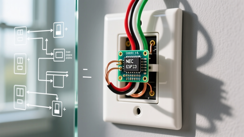

Introduction to GFCI Protection and Circuit Safety
Ground Fault Circuit Interrupters (GFCIs) are non-negotiable safety devices in modern electrical systems. According to the U.S. Consumer Product Safety Commission (CPSC), GFCIs have reduced residential electrocutions by over 80% since their widespread adoption. Whether you are upgrading an older kitchen, finishing a basement, or replacing a faulty receptacle in a bathroom, understanding the correct wiring diagram for a GFCI outlet is critical. A miswired GFCI won't just fail to protect you; it can create a false sense of security while leaving downstream circuits completely unprotected or causing immediate nuisance tripping.
This comprehensive reference guide breaks down the exact terminal anatomy, single-location versus multi-location wiring matrices, and the precise torque specifications required for 2026-compliant installations using industry-standard devices like the Leviton SmartlockPro 8599-W (15A) and Eaton GFTR20-W (20A).
Anatomy of a GFCI Receptacle: Line vs. Load
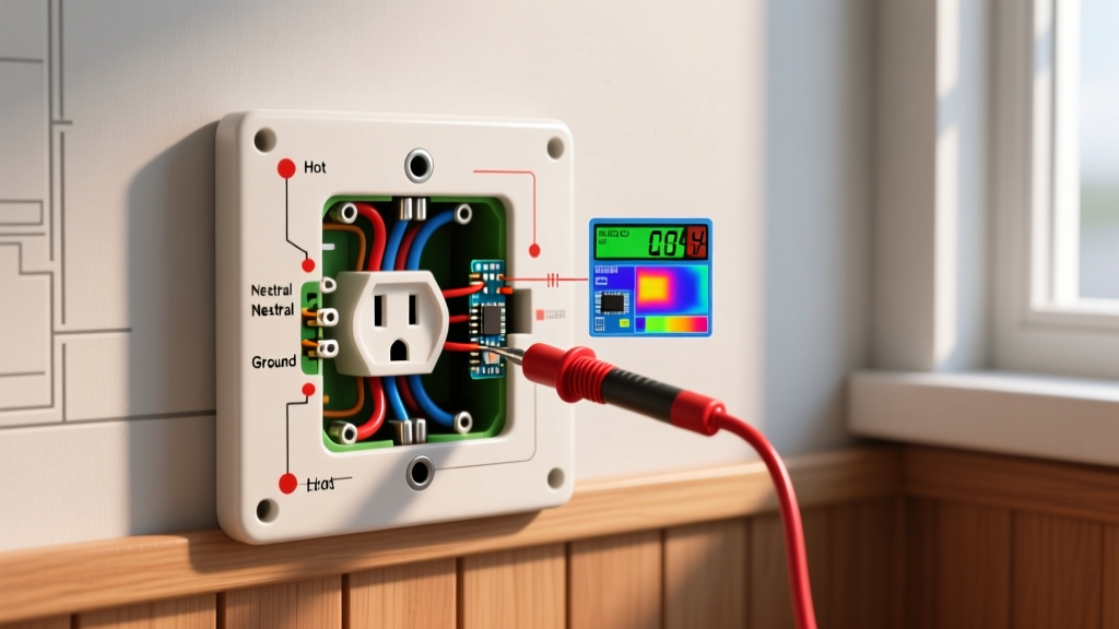
Unlike standard duplex receptacles, a GFCI outlet features two distinct sets of brass and silver terminals, plus a green grounding screw. Confusing these is the number one cause of installation failure.
- LINE Terminals (Brass/Silver): These connect to the incoming power source from your electrical panel. The black (hot) wire goes to the brass LINE screw, and the white (neutral) wire goes to the silver LINE screw.
- LOAD Terminals (Brass/Silver with Yellow Tape): These are used ONLY if you are protecting additional standard outlets downstream. They pass the GFCI-protected power to the next receptacle in the circuit.
- Ground Terminal (Green): Connects to the bare copper or green ground wire. Never omit this connection, even in older homes lacking a ground wire in the wall (though NEC rules for ungrounded replacements require specific 'No Equipment Ground' labeling).
Expert Insight: Modern GFCIs from manufacturers like Leviton and Eaton feature a built-in 'Line/Load Reversal' detection. If you accidentally swap the line and load wires, the device will refuse to reset, preventing a dangerous miswiring scenario. However, relying on this feature is poor practice; always verify your wires with a non-contact voltage tester before termination.
Wiring Diagram 1: Single-Location Protection
Use this configuration when the GFCI outlet is at the end of a circuit run, or when you only need to protect the specific receptacle itself (e.g., a standalone sump pump outlet or a dedicated bathroom vanity).
| Source Wire | GFCI Terminal | Terminal Color | Function |
|---|---|---|---|
| Black (Hot) | LINE | Brass | Delivers incoming 120V AC power |
| White (Neutral) | LINE | Silver | Completes the circuit back to panel |
| Bare/Green (Ground) | GROUND | Green | Provides fault path to earth |
| LOAD Terminals | N/A | Brass/Silver | Covered with yellow tape; left unused |
Cost Note: A standard 15A single-location GFCI like the Leviton 8599-W typically retails between $16 and $22 at major hardware suppliers.
Wiring Diagram 2: Multi-Location (Downstream) Protection
This is the most common residential configuration. By utilizing the LOAD terminals, a single GFCI can protect multiple standard duplex outlets downstream (e.g., protecting all kitchen counter outlets from a single point). The National Fire Protection Association (NFPA) outlines these requirements in NEC Article 210.8.
| Wire Source | GFCI Terminal | Destination | Crucial Warning |
|---|---|---|---|
| Panel Hot (Black) | LINE (Brass) | Incoming Power | Must be verified with a voltage tester |
| Panel Neutral (White) | LINE (Silver) | Incoming Power | Do not mix neutrals from other circuits |
| Downstream Hot (Black) | LOAD (Brass) | Next Outlet(s) | Provides GFCI protection to downstream |
| Downstream Neutral (White) | LOAD (Silver) | Next Outlet(s) | Must return to this specific GFCI only |
Step-by-Step Installation & Torque Specifications
Professional electricians do not just 'tighten screws until they feel tight.' The NEC now mandates adherence to manufacturer torque specifications to prevent thermal expansion failures and arcing.
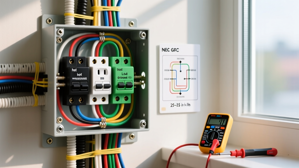
- Kill the Power: Turn off the 15A or 20A breaker. Verify zero voltage using a CAT III or CAT IV multimeter or non-contact tester.
- Strip the Wires: Use the built-in gauge on the back of the GFCI. For 14 AWG or 12 AWG solid copper wire, the strip length is exactly 5/8 inch. Do not nick the copper conductor.
- Form the Hook: If using side-wiring (screw terminals), use needle-nose pliers to form a clockwise hook. The clockwise direction ensures the screw pulls the wire tighter as it tightens.
- Apply Correct Torque: Using a calibrated torque screwdriver, tighten the terminal screws to the manufacturer's specification. For most Leviton and Eaton 15A/20A GFCIs, this is 14 in-lbs (inch-pounds). Over-tightening can strip the brass threads; under-tightening causes high-resistance hot spots.
- Wrap with Electrical Tape: While not strictly required by code if the box is properly sized, wrapping the sides of the GFCI with 3/4-inch Scotch 33+ vinyl tape covers the exposed terminal screws, preventing accidental shorts against metal junction boxes.
Troubleshooting Matrix: Common GFCI Failure Modes
Even with a perfect wiring diagram for a GFCI outlet, real-world conditions can cause issues. Use this matrix to diagnose problems.
| Symptom | Probable Cause | Diagnostic Fix |
|---|---|---|
| GFCI will not reset out of the box | Line and Load wires reversed | Swap the incoming power wires to the LINE terminals. |
| GFCI trips immediately upon reset | Shared Neutral (Multi-Wire Branch Circuit) | Ensure the neutral on the LOAD side does not share a return path with another breaker's hot wire. |
| Downstream outlets are dead | LOAD wires disconnected or tripped GFCI | Check LOAD terminal torque (14 in-lbs) and press the RESET button firmly. |
| GFCI trips when plugging in a specific tool | Tool has internal ground fault or high capacitive inrush | Test tool on a known-good circuit. Some older motors cause nuisance trips on highly sensitive modern GFCIs. |
| Test button does not trip the outlet | Defective internal solenoid or no ground | Replace the unit. Note: Some older GFCIs require a ground wire to test, but modern UL 943 listed units do not. |
NEC Code Requirements and 2026 Updates
The National Electrical Code (NEC) continuously expands GFCI requirements. As of the latest code cycles, GFCI protection is mandatory in kitchens, bathrooms, garages, accessory buildings, outdoors, crawl spaces, unfinished basements, laundry areas, and within 6 feet of wet bar sinks.
Furthermore, if you are working in a bedroom or living room where Arc Fault Circuit Interrupter (AFCI) protection is also required, you must use a Dual Function (DF) receptacle, such as the Eaton GFCI/AFCI Dual Function receptacles, or rely on a DF breaker in the panel. Standard GFCIs do not detect parallel or series arcing faults, which are a leading cause of electrical fires.
Final Safety Checklist
- Did you use a torque screwdriver set to 14 in-lbs?
- Are all downstream neutrals isolated from other circuits?
- Did you verify the 'Line/Load' orientation before pushing the receptacle into the box?
- Is the device rated for the correct amperage (15A on 14 AWG wire, 20A on 12 AWG wire)?
By strictly following this wiring diagram reference and respecting the physical limitations of the terminals, you ensure a safe, code-compliant installation that will protect your household from lethal ground faults for the next decade or more.