
Mastering the Inspection: Why the Diagram Matters
When inspecting or troubleshooting a dual-control ceiling fixture, relying on memory or guesswork is a recipe for miswired circuits, damaged equipment, and potential fire hazards. A precise wiring diagram for fan and light switch configurations serves as your primary diagnostic roadmap. Whether you are commissioning a new installation, upgrading to a smart home system, or diagnosing a flickering light and humming motor, understanding how to test the physical wiring against the schematic is a critical skill. As of the 2026 National Electrical Code (NEC) updates, strict adherence to proper conductor identification, AFCI protection, and grounding has become even more heavily enforced, making rigorous, methodical testing non-negotiable for any DIY electrician or home inspector.
Pre-Inspection Safety & Tool Calibration
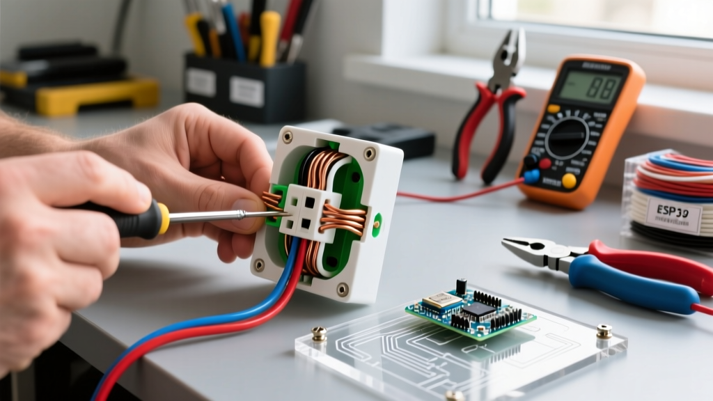
Before opening any junction box or switch plate, you must establish a safe testing environment. The OSHA Electrical Safety Guidelines dictate a strict Lockout/Tagout (LOTO) procedure for all dead-front testing. Ensure the circuit breaker is turned off and secured. For this inspection, you will need a calibrated True-RMS digital multimeter (such as the Fluke 117 or Klein Tools MM400), a non-contact voltage tester (NCVT) like the Klein NCVT-3, and a wire-tracing tone generator if the existing wiring lacks proper labeling.
- Verify Zero Energy: Test your NCVT on a known live circuit first to confirm the battery and sensor are functional, then test the target switch box.
- Check for Multi-Wire Branch Circuits (MWBC): If the switch box contains two hot wires on different phases (typically a red and black wire from a 12/3 or 14/3 cable connected to a double-pole breaker), you must shut off both breakers to eliminate the risk of shock from the shared neutral.
Decoding the Wiring Diagram for Fan and Light Switch
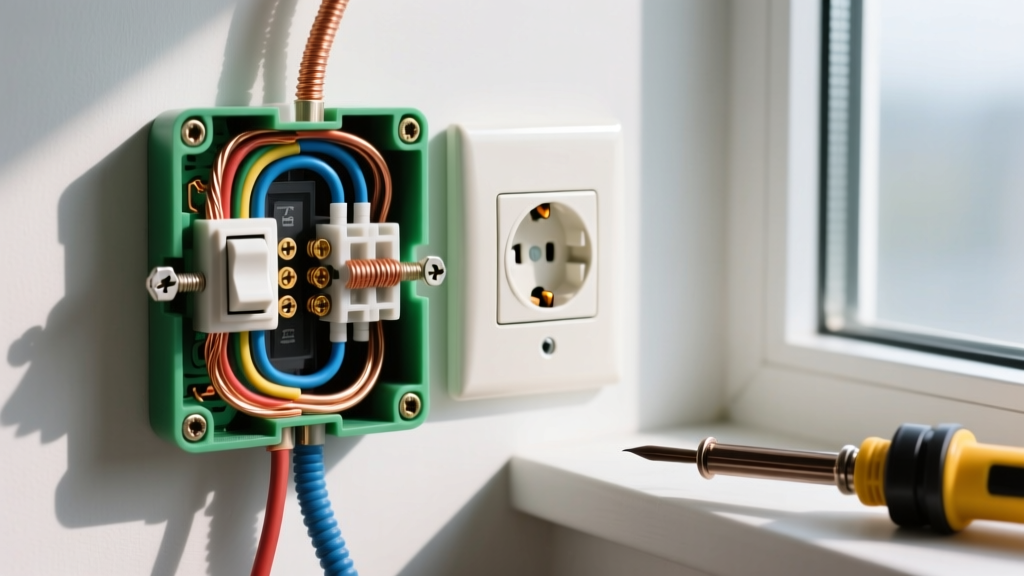
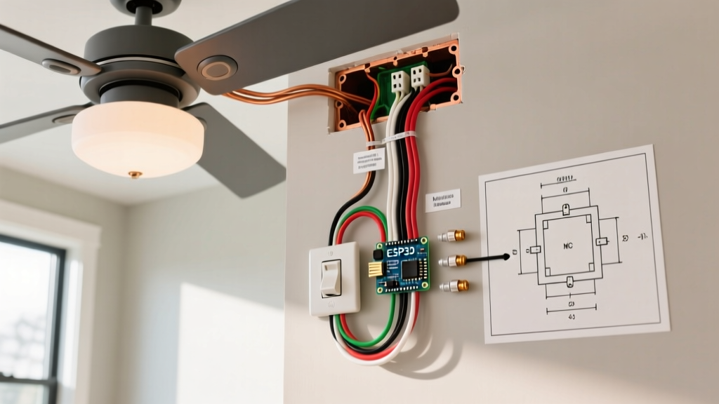
Standard independent control of a ceiling fan and light kit requires a 3-wire cable (e.g., 14/3 NM-B for 15-amp circuits or 12/3 NM-B for 20-amp circuits) running from the switch box to the ceiling canopy. The wiring diagram for fan and light switch setups relies on separating the switched hot conductors. Below is the standard terminal mapping you should verify during your visual inspection.
| Cable Type | Wire Color | Function | Switch Terminal / Canopy Wire |
|---|---|---|---|
| 14/2 NM-B (Line) | Black | Line/Hot (Always On) | Brass / Common (Pigtailed to both switches) |
| 14/3 NM-B (Load) | Red | Switched Hot (Light) | Black Screw / Canopy Blue (Light) |
| 14/3 NM-B (Load) | Black | Switched Hot (Fan) | Blue Screw / Canopy Black (Motor) |
| 14/3 NM-B (Load) | White | Neutral (Return) | Silver Screw / Canopy White (Neutral) |
| Bare/Green | Copper/Green | Equipment Ground | Green Screw / Canopy Green |
During your visual inspection, look for compliance with NEC Article 404.2(A), which mandates that switches must break the ungrounded (hot) conductor, never the neutral. If you see white wires connected to the brass or colored screws of the switch, they are being used as hot conductors. According to the NFPA 70 (National Electrical Code) Section 200.7(C), these white wires must be permanently re-identified with black or red electrical tape or marker at both the switch and the canopy to indicate they are ungrounded conductors.
Step-by-Step Continuity & Voltage Testing
Once the visual inspection against the diagram is complete, proceed to electrical testing. This two-phase approach ensures both the integrity of the physical connections and the correct behavior of the circuit under load.
Phase 1: Dead-Front Continuity Testing (Power OFF)
Set your multimeter to the Ohms (Ω) or Continuity setting. Disconnect the switches from the wall to isolate them from the circuit.
- Switch Isolation: Place one probe on the common (hot) terminal of the fan switch and the other on the load terminal. Toggle the switch. You should read near 0.00 Ω (or hear a beep) when ON, and infinite resistance (OL) when OFF. Repeat for the light switch.
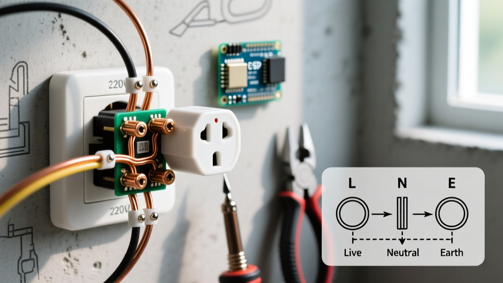
- Ground Continuity: Test from the switch box metal yoke (if metal) to the bare copper ground wire. You must have a continuous path to ground. If the box is plastic, ensure the ground pigtail is securely wire-nutted to the incoming bare copper and the switch's green ground screw.
- Short Circuit Check: Place probes between the red (light load) and black (fan load) wires at the switch box. The meter should read OL. If it reads continuity, you have a short in the ceiling canopy or a damaged 14/3 cable inside the wall.
Phase 2: Live Voltage Verification (Power ON)
Restore power at the breaker. Set your True-RMS multimeter to AC Voltage (VAC).
- Line Voltage Check: Measure between the incoming black hot wire and the bare ground. You should read between 118V and 122V (in North America). If you read significantly lower, investigate for voltage drop or a loose neutral at the panel.
- Switched Load Verification: Turn on the fan switch. Measure between the red wire (light load) and ground. It should read 0V. Measure between the black wire (fan load) and ground. It should read ~120V. Toggle the switches and verify the voltage shifts accordingly.
Common Failure Modes & Diagram Discrepancies
Even when installers claim to have followed the wiring diagram for fan and light switch layouts, field conditions often introduce errors. The Electrical Safety Foundation International (ESFI) frequently highlights improper wiring as a leading cause of residential electrical fires. Watch for these specific failure modes:
Critical Warning: The Dimmer/Motor Mismatch
Never wire a ceiling fan motor to a standard lighting dimmer circuit. Dimmers chop the AC sine wave to reduce voltage, which can destroy the fan's start capacitor, cause severe motor overheating, and create a fire hazard. Always verify the fan circuit is connected to a dedicated fan speed control (like the Lutron Maestro MACL-LFQ) or a standard toggle switch, while the light circuit handles the dimmer.
- Shared Neutral Violation: If the fan and light are on separate breakers but share a single neutral wire from a 14/3 cable, you have an illegal and dangerous MWBC setup without a handle-tie. The neutral can become overloaded if both loads run simultaneously, exceeding the wire's 15A ampacity.
- Ghost Voltage on Switched Legs: When testing the red or black load wires with a high-impedance digital multimeter, you may read 40V-70V even when the switch is OFF. This is induced 'ghost voltage' from the parallel wires in the 14/3 cable. Use the Lo-Z (Low Impedance) setting on your Fluke 117 to bleed off this phantom voltage and confirm a true 0V reading.
- LED Flicker on Light Circuit: If the light circuit is wired to an older, non-LED-compatible dimmer, the low-wattage draw of modern LED fan light kits will cause strobing or ghosting. Upgrade to a 2026-compliant smart dimmer with adjustable low-end trim.
Smart Switch Retrofitting & 2026 Standards
If you are upgrading to a smart switch system (such as Leviton Decora Smart or Lutron Caseta), the traditional wiring diagram changes. Most smart fan/light combo switches require a dedicated neutral wire at the switch box to power the internal Wi-Fi/Zigbee radio. If your older home only has a 14/2 cable running to the switch (using the white wire as a switched hot), you cannot install a standard smart switch without pulling a new 14/3 cable or utilizing a smart canopy module (like the Bond Bridge or a Lutron Caseta P-FAN-P2) that resides in the ceiling canopy and requires only a single hot and neutral at the wall.
Frequently Asked Questions (FAQ)
Can I use 14/2 wire to wire a fan and light switch independently?
No. A 14/2 cable only provides one hot, one neutral, and one ground. This allows you to switch the fan and light together on a single toggle. For independent control from the wall, you must use a 14/3 cable to provide two separate switched hot conductors. Alternatively, you can use 14/2 if you install a smart canopy receiver that uses a remote or single smart switch to digitally separate the fan and light signals.
Why does my fan hum when the light is turned on?
This usually indicates a shared neutral issue, a poorly isolated dimmer causing harmonic distortion on the circuit, or that the fan motor is incorrectly wired in series with the light kit rather than in parallel. Verify your physical wiring against the manufacturer's schematic to ensure the blue (light) and black (motor) canopy wires are connected to their respective independent wall switch loads.
Do I need AFCI protection for this circuit?
Yes. Under the 2026 NEC guidelines, virtually all 15A and 20A, 120V branch circuits supplying outlets and switches in living areas, bedrooms, and hallways require Arc-Fault Circuit Interrupter (AFCI) protection. Ensure the breaker powering your fan and light switch is a combination-type AFCI breaker.