
Understanding the Reset Button Electrical Outlet
When homeowners and DIYers refer to a "reset button electrical outlet," they are almost exclusively talking about a Ground Fault Circuit Interrupter (GFCI) receptacle. In 2026, these devices are mandatory in all wet and damp locations—including kitchens, bathrooms, garages, outdoors, and crawlspaces—per the National Electrical Code (NEC). More recently, Dual-Function (DF) receptacles, which combine GFCI and Arc Fault Circuit Interrupter (AFCI) protection into a single device with a reset button, have become the standard for laundry rooms and kitchens.
Wiring a reset button electrical outlet is fundamentally different from wiring a standard duplex receptacle. The internal sensing circuitry requires strict adherence to line and load designations. Miswiring these terminals is the leading cause of a reset button that refuses to stay engaged or fails to protect downstream outlets. This wiring diagram reference will guide you through single-location and multi-location GFCI installations, complete with troubleshooting protocols for the reset mechanism.
The Golden Rule: Line vs. Load Terminals
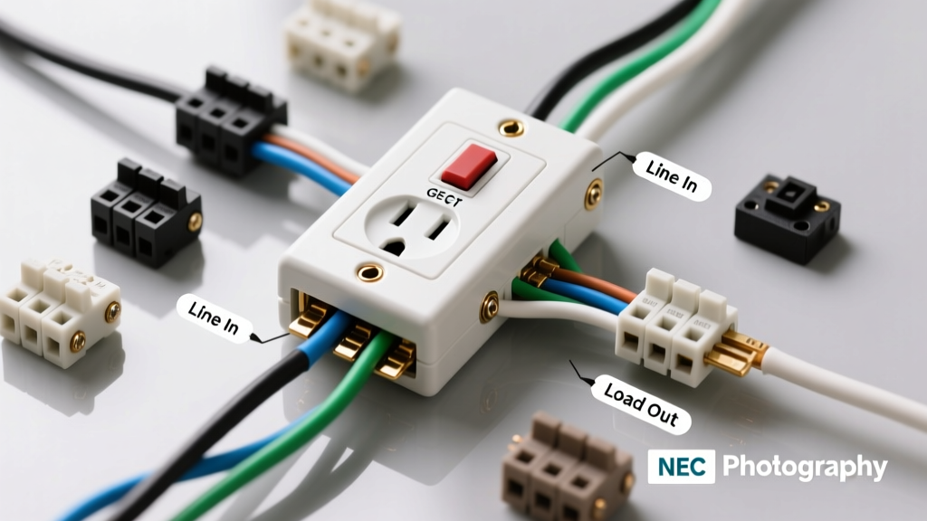
Before touching a wire stripper, you must understand the terminal designations on the back of a GFCI receptacle (such as the popular Leviton 2091 SmartlockPro or Hubbell GF520). Unlike standard outlets where either set of brass screws can accept the incoming power, a reset button electrical outlet has two distinct sets of terminals:
- LINE Terminals: These connect to the incoming power source from your electrical panel. The black (hot) wire goes to the brass LINE screw, and the white (neutral) wire goes to the silver LINE screw.
- LOAD Terminals: These connect to downstream standard outlets, extending GFCI protection to other devices on the same circuit. If you are only protecting the single GFCI outlet itself, the LOAD terminals remain empty, and the yellow warning tape covering them should not be removed.
Expert Insight: According to the National Fire Protection Association (NFPA), reverse wiring (connecting incoming power to the LOAD terminals) will allow the outlet to power a device, but the reset button will not trip during a ground fault, rendering the safety mechanism completely useless.
Wiring Diagram 1: Single-Location Protection (Line Only)
Use this configuration when you are replacing an existing standard outlet at the end of a circuit run, or when local code does not require downstream protection. This is the most common and foolproof wiring method.
Step-by-Step Connection Guide
- Verify Power: Turn off the circuit breaker and verify zero voltage using a non-contact voltage tester (NCVT) and a multimeter.
- Identify the Source: Locate the single set of hot (black) and neutral (white) wires in the electrical box.
- Connect the Ground: Attach the bare copper or green ground wire to the green grounding screw on the GFCI. Loop it clockwise and tighten.
- Connect the Neutral: Attach the white neutral wire to the silver screw marked LINE.
- Connect the Hot: Attach the black hot wire to the brass screw marked LINE.
- Leave Load Empty: Do not remove the yellow tape covering the LOAD terminals.
Wiring Diagram 2: Multi-Location Protection (Line and Load)
Use this configuration when you want a single reset button electrical outlet to protect downstream standard receptacles (e.g., a bathroom GFCI protecting a downstream standard outlet near the mirror).
Step-by-Step Connection Guide
- Identify Line vs. Load Wires: You will have two sets of hot and neutral wires. Temporarily cap all wires, turn the breaker on, and use a multimeter to identify which pair has 120V. This is your LINE pair. Turn the breaker back off.
- Connect Grounds: Pigtail both bare ground wires together and attach them to the GFCI ground screw.
- Connect LINE Neutral & Hot: Attach the incoming source white wire to the silver LINE screw, and the incoming black wire to the brass LINE screw.
- Connect LOAD Neutral & Hot: Attach the downstream white wire to the silver LOAD screw, and the downstream black wire to the brass LOAD screw.
Receptacle Comparison Matrix: Standard vs. GFCI vs. AFCI vs. DF
Not all reset button electrical outlets serve the same purpose. The table below outlines the specific applications and trip thresholds for modern receptacles available in 2026.
| Receptacle Type | Reset Button Color | Primary Protection | Trip Threshold | Typical Cost (2026) |
|---|---|---|---|---|
| Standard Duplex | N/A (No button) | Overcurrent (via breaker) | N/A | $1.50 - $3.00 |
| GFCI (Class A) | Red or Black | Ground Fault (Shock) | 4mA to 6mA | $15.00 - $22.00 |
| AFCI | Blue or Purple | Arc Fault (Fire) | Parallel/Series Arc | $25.00 - $35.00 |
| Dual-Function (DF) | Red/Blue Combo | Ground & Arc Fault | 4-6mA / Arc | $38.00 - $48.00 |
Troubleshooting: Why Won't the Reset Button Stay In?
The most frequent support query we receive involves a reset button electrical outlet that clicks but immediately pops back out, or feels "mushy" when pressed. Here is the diagnostic framework for the three most common failure modes.
1. The "Mushy" Button (End of Life or Internal Failure)
If the reset button offers no mechanical resistance and fails to click, the internal solenoid has likely failed, or the device has reached its End of Life (EOL). Modern GFCIs (manufactured after 2006) feature an EOL mechanism that permanently disables the reset function when the internal sensing circuitry degrades. Fix: Replace the receptacle. GFCIs typically last 10 to 15 years.
2. The "Pop-Out" Button (Active Ground Fault)
If the button clicks into place but immediately trips back out, the GFCI is doing its job: it is detecting an active ground fault of 4-6mA. This could be caused by a faulty appliance plugged into the circuit, moisture inside an outdoor junction box, or a pinched wire in the wall. Fix: Unplug all devices on the circuit. If the button stays in, the fault is in an appliance. If it still trips, inspect downstream LOAD wiring for moisture or damaged insulation.
3. The "Reverse Polarity" Trip
If you wired the incoming power to the LOAD terminals and the downstream devices to the LINE terminals, the GFCI's internal self-test will detect the miswiring upon reset and immediately trip the device. Fix: Remove the receptacle, verify the incoming hot wire with a multimeter, and re-terminate to the correct LINE terminals.
Pro Installation Specs: Torque and Box Fill
A hidden cause of nuisance tripping in reset button electrical outlets—particularly AFCI and Dual-Function models—is a loose neutral wire. A loose neutral creates micro-arcing, which the AFCI sensor interprets as a dangerous series arc.
- Torque Specifications: Always use a calibrated torque screwdriver. The industry standard for 14 AWG and 12 AWG copper wire on 15A and 20A receptacle terminal screws is 14 inch-pounds (in-lbs). Hand-tightening is no longer considered best practice and can violate NEC 110.14(D) requirements for torque verification.
- Box Fill Capacity: GFCI and DF receptacles are significantly deeper than standard outlets (often exceeding 1.5 inches in depth). Ensure your electrical box has adequate cubic inch capacity. A standard 20-cubic-inch "old work" box is usually sufficient for a single GFCI, but if you are pigtailing multiple load wires, you may need a 22 or 24-cubic-inch deep box to prevent crushing the wires against the internal circuit board.
Safety and Compliance
Working with 120V AC line voltage carries a risk of lethal shock and electrical fire. Always verify the absence of voltage before beginning work. For comprehensive safety guidelines and to understand the life-saving statistics behind GFCI technology, refer to the Consumer Product Safety Commission (CPSC) Electrical Safety Center. If you are unsure about identifying line and load conductors in older homes with unmarked wiring, consult a licensed electrician. Proper installation of a reset button electrical outlet is not just about restoring power; it is about ensuring the critical safety mechanisms function exactly as engineered during a fault event.