
The 'What Plug Is This?' Dilemma: Decoding NEMA Configurations
If you have found yourself staring at a heavy-duty electrical connector, searching for a wiring diagram for this plug, you are not alone. The transition toward home EV charging, backup power generation, and modern RV camping has brought industrial-grade electrical hardware into residential garages and driveways. However, unlike standard 15-amp household outlets, high-amperage plugs utilize specialized National Electrical Manufacturers Association (NEMA) configurations that dictate specific voltage, amperage, and phase requirements.
Misidentifying a plug or misinterpreting its pinout can lead to catastrophic equipment failure, voided warranties, or severe electrical fires. According to the National Fire Protection Association (NFPA 70), improper termination and overloaded circuits remain leading causes of residential electrical fires. This guide will help you definitively identify 'this plug' in your hand and provide the exact wiring diagrams, torque specifications, and code-compliant installation practices for the three most common high-amperage scenarios.
Identification Matrix: Match Your Hardware
Before consulting a wiring diagram, you must verify the NEMA designation stamped onto the face of the receptacle or the collar of the plug cap. Use the matrix below to identify your specific hardware.
| NEMA Code | Prong Count | Blade Style | Voltage / Amperage | Primary Application |
|---|---|---|---|---|
| 14-50 | 4 Prong | Straight Blade | 125/250V / 50A | EV Chargers, Electric Ranges, Welders |
| L14-30 | 4 Prong | Twist-Lock | 125/250V / 30A | Generators, Manual Transfer Switches |
| TT-30 | 3 Prong | Angled Blade | 125V / 30A | RV Park Receptacles, Travel Trailers |
| 14-30 | 4 Prong | Straight Blade | 125/250V / 30A | Electric Dryers |
Scenario 1: NEMA 14-50 (EV Chargers & Electric Ranges)
The NEMA 14-50 is the undisputed king of modern residential high-power applications. With the 2026 EV market heavily favoring plug-in architectures over hardwired setups for portability, the 14-50R receptacle is in higher demand than ever.
Pinout and Wiring Diagram
When looking at the face of a 14-50 receptacle (ground pin at the bottom), the terminal assignments are as follows:
- X (Left Slot): Hot 1 (Black wire) - 120V to Neutral, 240V to Y
- Y (Right Slot): Hot 2 (Red wire) - 120V to Neutral, 240V to X
- W (Top/Neutral Slot): Neutral (White wire) - Required for 120V appliances like ranges
- G (Bottom Pin): Ground (Bare or Green wire) - Safety earth
Expert Insights & Code Compliance
Wire Gauge Sizing: A common and dangerous DIY mistake is using 6 AWG NM-B (Romex) on a 50-amp breaker. Under NEC Article 334.80, NM-B cable is restricted to the 60°C column of the ampacity table, meaning 6 AWG copper is only rated for 55 amps. For a 50-amp continuous load (like an EV charger), you must use 4 AWG NM-B or 6 AWG THHN/THWN pulled through conduit. The Alternative Fuels Data Center (AFDC) strongly recommends conduit runs for EV infrastructure to manage thermal dissipation.
The GFCI Nuance: Recent NEC cycles (2020/2023/2026) mandate GFCI protection for 14-50 receptacles installed in garages (NEC 210.8(F)). Many older or poorly designed EV chargers induce a slight ground-to-neutral leakage during startup, which will instantly trip a 50A GFCI breaker. If your EV charger trips the breaker, do not remove the GFCI protection; instead, upgrade to a premium UL-listed charger with isolated ground circuitry, or hardwire the unit (which bypasses the receptacle GFCI requirement).
Scenario 2: NEMA L14-30 (Generator Transfer Switches)
The 'L' in L14-30 stands for 'Locking.' This twist-lock plug is designed for portable generators (such as the Generac GP3300 or Honda EU7000is) connecting to a manual transfer switch inlet box (like the Reliance Controls PB30). The twisting collar ensures the plug cannot vibrate loose under heavy mechanical load or outdoor weather conditions.
Pinout and Wiring Diagram
The L14-30 features four blades arranged in a circle with a central locking pin. When wiring the male plug cap (e.g., Leviton L14-30P):
- X (Brass Screw): Hot 1 (Black)
- Y (Brass Screw): Hot 2 (Red)
- W (Silver Screw): Neutral (White)
- G (Green Screw): Ground (Green/Bare)
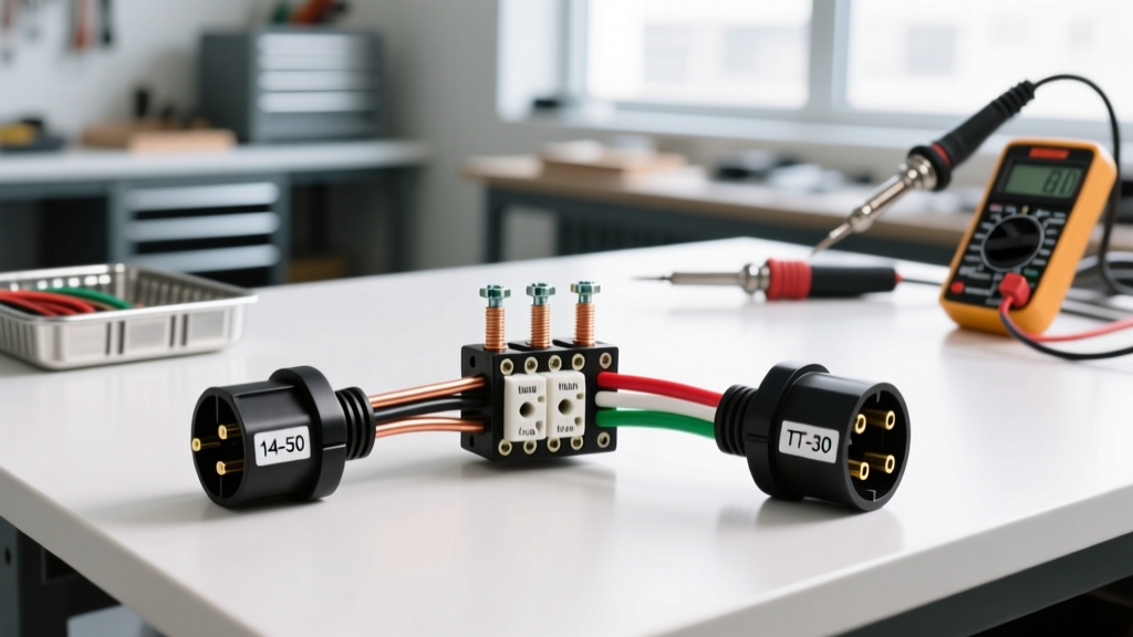
Critical Safety Warning: Never wire a generator plug to backfeed a home panel without a certified, mechanically interlocked transfer switch. Backfeeding via a 'suicide cord' (a male-to-male plug) is illegal, violates OSHA Electrical Safety Standards, and can electrocute utility line workers repairing downed grids.
Termination Best Practices
Because L14-30 plugs are frequently handled, dropped, and exposed to moisture, strain relief is paramount. Ensure the internal cord grip clamp is tightened securely over the outer jacket of the SOOW cable, not just the individual inner wires. A 10/4 SOOW cable is the industry standard for 30-amp generator cords, providing oil and water resistance.
Scenario 3: NEMA TT-30 (RV Park Receptacles)
The TT-30 (Travel Trailer 30-Amp) is a notorious source of confusion. It features three angled prongs and looks remarkably similar to a NEMA 10-30 (an obsolete 3-prong dryer plug). However, their electrical profiles are entirely different.
The 120V vs. 240V Trap
The TT-30 is strictly a 120-volt, 30-amp single-phase receptacle. The pinout consists of one Hot (Black), one Neutral (White), and one Ground (Green). Conversely, a dryer plug (10-30 or 14-30) supplies 240 volts. If an RV owner mistakenly wires a TT-30 plug cap to a 240V dryer outlet, or if a campground owner miswires a TT-30R receptacle with 240V, it will instantly destroy the RV's power converter, fry internal appliances, and likely ignite a fire.
When wiring a TT-30R receptacle:
- Hot (Brass): Black wire (120V)
- Neutral (Silver): White wire
- Ground (Green): Bare/Green wire
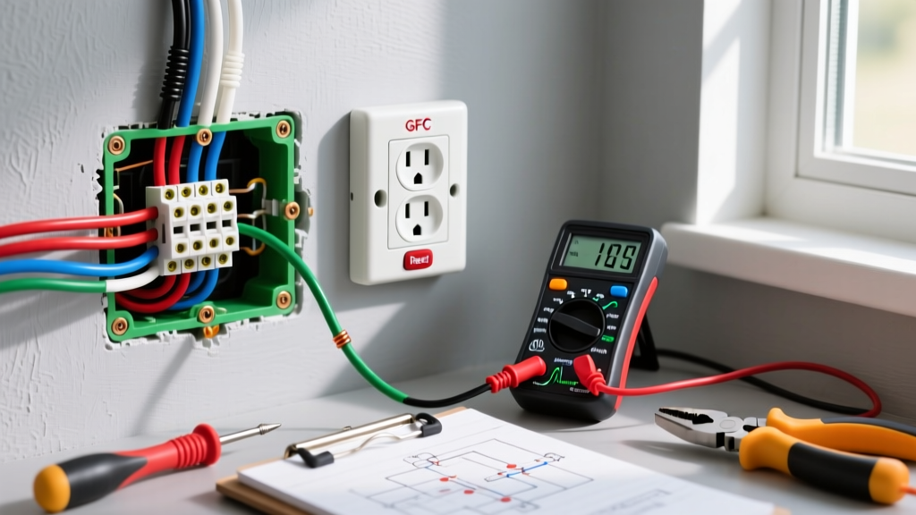
Always verify the voltage at a TT-30 receptacle with a multimeter before plugging in an RV. You should read exactly 120V (+/- 5%) between Hot and Neutral, and 0V between Neutral and Ground.
Critical Termination Specs: Torque and Thermal Management
Having the correct wiring diagram for this plug is only half the battle; the physical termination dictates the longevity of the installation. High-amperage circuits generate significant heat. If a terminal screw is under-torqued, the increased electrical resistance creates a thermal feedback loop, eventually melting the receptacle face.
Torque Specifications
Do not rely on the 'tighten it until it hurts' method. Premium receptacles like the Hubbell HBL9450A (Industrial Grade 14-50R, typically $85-$110) and the Leviton 279-S00 (Residential Grade, typically $12-$15) publish specific torque requirements on their instruction sheets. Most 50-amp terminal screws require between 75 in-lbs and 90 in-lbs of torque.
Invest in a calibrated torque screwdriver, such as the Klein Tools 32500 series or a Wiha insulated torque driver. Furthermore, strip the wire insulation exactly to the gauge marked on the receptacle. Exposed bare copper outside the terminal block invites accidental shorting, while insulation pushed into the terminal block creates a high-resistance connection.
Frequently Asked Questions
Can I use a NEMA 14-30 (Dryer) plug for my MIG welder?
It depends on the welder's duty cycle and amperage draw. Many modern inverter-based welders (like the Lincoln Electric Power MIG 210) can operate on a 30-amp circuit. However, you must swap the plug cap to a NEMA 14-30P and ensure the breaker is sized to 30A. Never adapter a 14-30 wall outlet to a 14-50 plug cap using a passive dongle to draw 50 amps; the 30A breaker will trip, or worse, the wiring will overheat if the breaker fails.
Why is my 14-50 outlet melting at the terminals?
Melting is almost always caused by loose terminal connections leading to electrical arcing and thermal runaway, or by using a residential-grade receptacle (like the $12 Leviton) for a continuous 40-amp EV charging load. For daily EV charging, always upgrade to an industrial-grade receptacle (Hubbell or Bryant) featuring heavy-duty copper-alloy terminal clamps that resist thermal creep.
Do I need to bond the neutral and ground on my generator's L14-30 outlet?
No. When connecting a generator to a home transfer switch, the generator acts as a separately derived system. The neutral-to-ground bond must occur at the main service panel or at the generator's internal bonding jumper, but never at both simultaneously. Creating parallel neutral-ground paths will cause stray currents to flow through the grounding wire, creating a severe shock hazard.