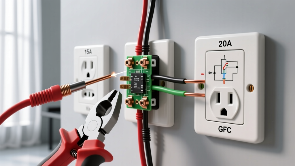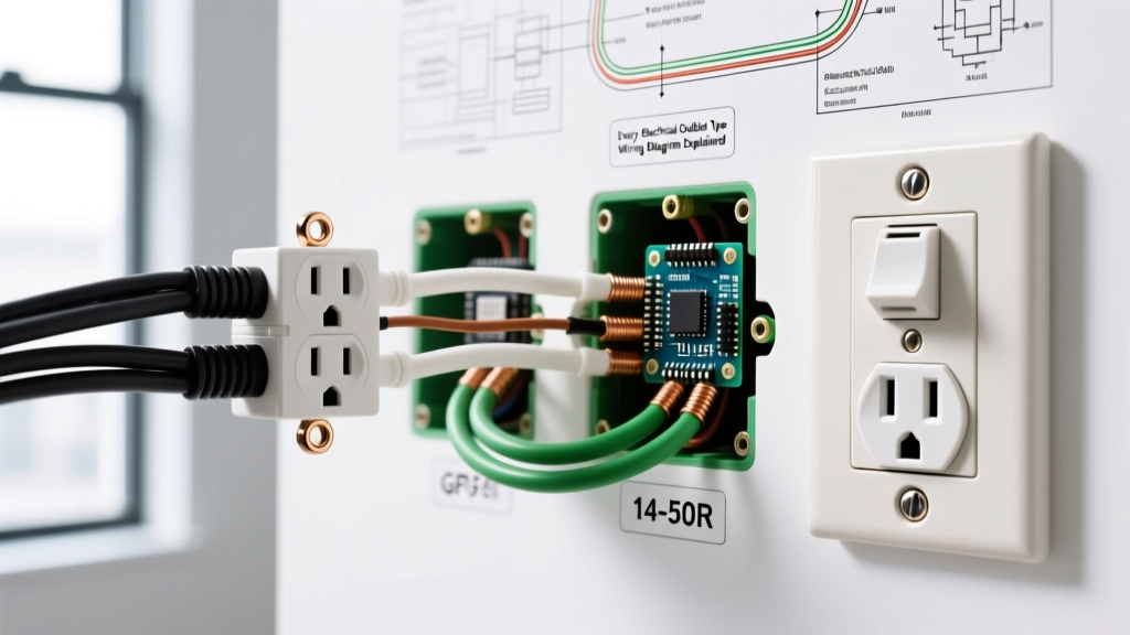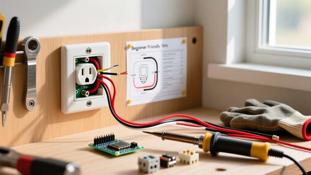

The Reality of 120V AC: Why Safety Protocols Matter
Working with household electricity is one of the most rewarding DIY skills you can learn, but it carries inherent risks. An electric shock from outlet terminals during a replacement or installation project is a common hazard for beginners who bypass critical safety steps. While 120 volts might seem manageable compared to high-voltage industrial lines, it is more than enough to cause ventricular fibrillation, severe burns, or fatal electrocution if current crosses the heart.
This beginner installation tutorial focuses on the exact protocols, tools, and wiring techniques required to install a standard 15-amp tamper-resistant receptacle while guaranteeing your physical safety. As of 2026, modern electrical codes and tooling have made DIY wiring safer than ever, provided you respect the physics of the circuit.
⚠️ CRITICAL SAFETY WARNING: Never assume a circuit is dead based on a wall switch position or a tripped breaker label. Panel labels in older homes are notoriously inaccurate. You must verify the absence of voltage at the outlet box itself before touching any bare copper.
Essential Safety Gear & Diagnostic Tools
To prevent an electric shock from outlet wiring, you must invest in insulated tools and reliable testers. Relying on a cheap, uncalibrated voltage pen is a leading cause of DIY electrical accidents.
- Non-Contact Voltage Tester (NCVT): The Klein Tools NCVT-4 ($28–$35) is a dual-range tester that detects both standard 120V and low-voltage doorbell wires. It provides visual and audible alerts without requiring bare metal contact.
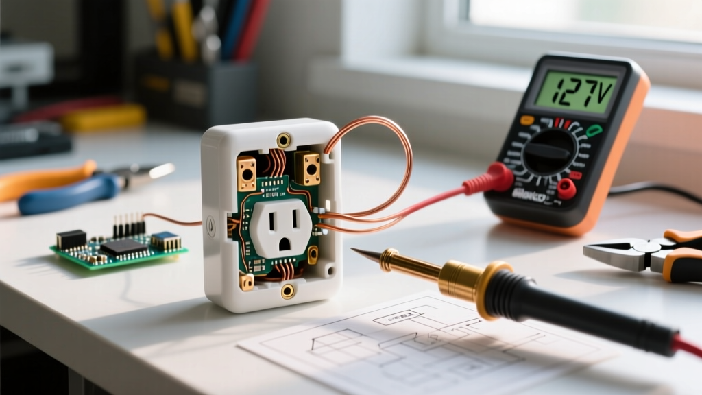
- Digital Multimeter (DMM): The Fluke 117 True-RMS Multimeter ($180–$200) features VoltAlert technology and CAT III 600V safety ratings, ensuring internal fuses won't rupture if you accidentally test a live 240V circuit.
- Insulated Screwdrivers: Look for VDE-rated or OSHA-compliant insulated drivers, such as the Milwaukee 48-22-2205 set ($18–$25). These feature a 1000V-rated dielectric coating that acts as a secondary barrier if your primary shutoff fails.
- Torque Screwdriver: The IDEAL 30-512 TorqueLOK ($85–$95) ensures terminal screws are tightened to exact manufacturer specifications, preventing arcing and subsequent shock hazards from loose connections.
Step-by-Step Safe Outlet Installation Protocol
Step 1: Panel Shutoff and Lockout/Tagout (LOTO)
Navigate to your main electrical panel and flip the breaker corresponding to the room you are working in to the OFF position. For maximum safety, apply a physical Lockout/Tagout (LOTO) device to the breaker. According to the Occupational Safety and Health Administration (OSHA), LOTO procedures prevent accidental re-energization by other household members while you are working with exposed conductors.
Step 2: The 3-Point Verification Test
Before removing the outlet cover plate, perform a 3-point test using your NCVT or Multimeter:
- Test a Known Live Source: Verify your tester works on an outlet you know is powered (e.g., in a different room).
- Test the Target Outlet: Insert the tester into both slots of the target receptacle and touch it to the center screw of the cover plate.
- Re-Test the Known Live Source: Confirm the tester still works to ensure the battery didn't die during the process.
Step 3: Safe Wire Stripping and Preparation
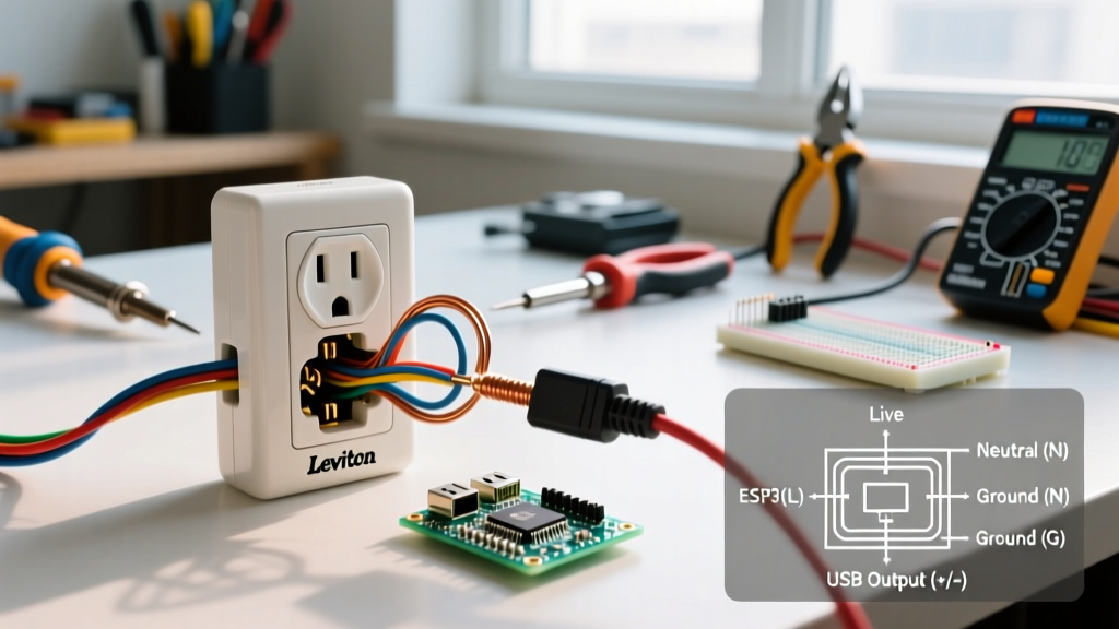
Once the box is verified dead, unscrew the receptacle. If you are installing a new Leviton T5320-W 15A Tamper-Resistant Duplex Receptacle (approx. $3.50), strip exactly 3/4 inch of insulation from your 14 AWG solid copper wires. Never nick the copper conductor with your wire strippers. A nicked wire creates a high-resistance hotspot that can melt the insulation over time, exposing live voltage and creating a severe shock and fire hazard.
Step 4: Making Secure, Shock-Free Terminations
Always use the side-wiring terminal screws rather than the push-in backstab holes. Backstab connections rely on a tiny internal spring that can loosen due to thermal expansion and contraction. A loose neutral wire can cause the metal faceplate or connected appliance chassis to become energized, resulting in an unexpected electric shock from outlet components when touched.
Wrap the bare copper wire clockwise around the terminal screw so that tightening the screw pulls the loop tighter. As mandated by recent updates to the National Electrical Code (NEC), use a torque screwdriver set to the manufacturer's specification (typically 12 to 14 inch-pounds for standard 15A receptacles) to ensure a flawless mechanical connection.
Common Wiring Mistakes That Cause Shock Hazards
Understanding failure modes is critical for DIYers. The table below outlines mistakes that directly lead to an electric shock from outlet boxes or connected devices.
| Wiring Mistake | The Danger / Consequence | Prevention Strategy |
|---|---|---|
| Bootleg Ground | Jumpering the neutral and ground terminals to trick a tester. If the neutral breaks upstream, the entire appliance chassis becomes energized at 120V. | Never bond neutral and ground at the receptacle. If no ground wire exists, install a GFCI receptacle and label it 'No Equipment Ground'. |
| Reversed Polarity | Swapping the hot (brass) and neutral (silver) wires. The appliance works, but the internal switch only breaks the neutral, leaving internal components live. | Always connect the black (hot) wire to the brass screw and the white (neutral) wire to the silver screw. |
| Over-Stripping Wire | Leaving more than 3/4" of bare copper exposed. Exposed live wire can touch the metal outlet box or a grounded user's hand. | Use the built-in gauge on the back of the receptacle to measure exact strip length. Wrap electrical tape around the sides of the terminals as a secondary barrier. |
The Role of Tamper-Resistant (TR) Shutters
If you are replacing an older receptacle, you must install a Tamper-Resistant (TR) model. According to the Consumer Product Safety Commission (CPSC), TR receptacles feature internal spring-loaded shutters that block foreign objects from entering the energized slots. These shutters only open when equal pressure is applied to both slots simultaneously (as happens when inserting a standard 2-prong or 3-prong plug). This mechanical interlock is your primary defense against children suffering an electric shock from outlet slots.
Post-Installation Verification
Once the receptacle is mounted and the cover plate is secured, restore power at the breaker panel. Do not rely solely on plugging in a lamp to verify your work. Use a dedicated receptacle tester, such as the Gardner Bender GFI-3501 ($12–$15). This device uses a matrix of three LED lights to instantly confirm correct wiring, open grounds, or reversed polarity. If the tester indicates an open ground or hot/neutral reverse, turn the breaker back off immediately and re-evaluate your terminations.
When to Abort and Call a Professional
As a beginner, you should halt your installation and hire a licensed electrician if you encounter:
- Aluminum Wiring: Requires specialized CO/ALR rated receptacles and anti-oxidant paste to prevent galvanic corrosion and subsequent arcing/shocks.
- Federal Pacific or Zinsco Panels: These legacy panels are known to fail internally, meaning the breaker may remain energized even when flipped to the OFF position.
- Unidentified Wires: If you open the box and find more than two sets of cables (indicating a complex daisy-chain or switch loop) and cannot map them, do not guess.
By strictly adhering to verification protocols, utilizing insulated diagnostic tools, and respecting NEC torque specifications, you can confidently upgrade your home's electrical infrastructure while entirely eliminating the risk of an electric shock from outlet installations.