
Decoding the Wiring Diagram for 3 Light Switches in a 3-Gang Box
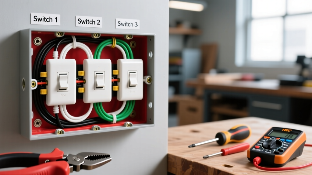
Wiring a 3-gang electrical box is one of the most common yet intimidating tasks for DIYers and apprentice electricians. When you are looking for a reliable wiring diagram for 3 light switches, the complexity does not just come from the switches themselves, but from the sheer volume of conductors crowding a single junction point. A standard 3-gang setup controlling three separate light fixtures requires meticulous wire management, strict adherence to box-fill calculations, and proper pigtailing techniques to ensure a safe, long-lasting installation.
This reference guide breaks down the exact topology, NEC (National Electrical Code) requirements, and step-by-step execution for wiring three single-pole switches in one enclosure. We will also cover the critical edge case of integrating a 3-way switch into the same gang box.
⚠️ Critical Safety & NEC Box Fill Warning
Before touching a single wire, you must verify your box volume. According to NFPA 70 (NEC Article 314.16), a standard 3-gang setup with 14 AWG wire requires a minimum box volume of 30 cubic inches. However, to accommodate the stiffness of modern NM-B (Romex) cables and smart switch depths, we strongly mandate using a 54 cubic inch 3-gang box (such as the Carlon B630R). Overcrowding causes wire insulation damage and overheating.
Scenario A: Three Single-Pole Switches (Standard Topology)
The most frequent application for a 3-gang box is controlling three separate lighting zones (e.g., kitchen overheads, under-cabinet LEDs, and an adjacent dining room chandelier) from a single wall location. In this scenario, you are dealing with one incoming power feed and three outgoing load feeds.
Conductor Mapping Matrix
Understanding the flow of current is vital. The table below maps the exact conductor count and function for a standard 15-Amp circuit utilizing 14/2 NM-B cable.
| Wire Color | Function | Quantity in Box | Termination Point |
|---|---|---|---|
| Black (Line) | Incoming 120V Hot | 1 | Pigtailed to all 3 switch brass screws |
| Black (Load) | Outgoing to Fixtures | 3 | One per switch brass screw (via pigtail) |
| White (Neutral) | Return Path | 4 (1 in, 3 out) | Wire-nutted together; NOT connected to standard switches |
| Bare/Green | Equipment Ground | 4 + 1 pigtail | Bonded together and pigtailed to metal box/switch green screws |
Step-by-Step Execution & Pigtailing Strategy
Daisy-chaining the hot wire through the terminal screws of adjacent switches is a severe code violation and a fire hazard. If one switch is removed or fails, it breaks the circuit for the downstream switches. You must use pigtails.
- Prepare the Incoming Feed: Strip 3/4 inch of insulation from the incoming 14/2 NM-B black (hot) wire.
- Create the Hot Pigtail Bundle: Cut three 6-inch lengths of 14 AWG solid black THHN wire. Strip 1/2 inch from each end. Insert the incoming hot wire and the three black pigtails into a Wago 221-3 Lever Nut. (Lever nuts are superior to twist-on wire nuts for 3-gang boxes as they reduce bulk and eliminate the torque required to twist four stiff wires together).
- Bundle the Neutrals: Take the incoming white neutral and the three outgoing white neutrals. Strip 3/4 inch and secure them in a second Wago 221-5 (5-port) lever nut. Note: Standard single-pole switches do not use the neutral wire. Do not cap a neutral to the switch's green ground screw.
- Bond the Grounds: Twist the four bare ground wires together with a copper crimp sleeve or a green Ideal 341 wire nut, leaving a 6-inch bare copper pigtail extending out. If using a metal 3-gang box, you must add a second pigtail to bond the box's internal grounding clip.
- Terminate the Switches: Connect one black pigtail to the brass 'LINE' terminal of each switch. Connect the three outgoing black (load) wires to the brass 'LOAD' terminals. Finally, loop the ground pigtail around the green grounding screws on all three switch yokes.
- Fold and Seat: Carefully fold the Wago connectors into the back corners of the 54 cu. in. box. Push the switches in simultaneously, ensuring no ground wires are pinched behind the yoke straps.
Expert Edge Case: Multi-Wire Branch Circuits (MWBC)
If your 3-gang box is fed by a Multi-Wire Branch Circuit (two hot wires sharing a single neutral on opposite phases), the wiring diagram changes drastically. According to NEC 210.4, the simultaneous disconnect rule applies. You must install a 2-pole breaker with a handle tie in the main panel. Furthermore, the neutral wires must be pigtailed in the box before splicing to the outgoing loads; you cannot rely on the device yoke to carry the neutral return current, as removing one switch would open the neutral path for the other phase, potentially sending 240V through your 120V lighting fixtures and destroying them.
Scenario B: Integrating a 3-Way Switch in a 3-Gang Box
Often, a 3-gang box houses two single-pole switches and one 3-way switch (used for hallway or stairway control). The wiring diagram for 3 light switches in this hybrid configuration requires managing 'traveler' wires.
- Switch 1 & 2 (Single-Pole): Wired exactly as detailed in Scenario A.
- Switch 3 (3-Way, e.g., Leviton 5604): The incoming hot (or load) connects to the black 'Common' terminal. The Red and Black traveler wires from the /3 cable connect to the two brass traveler terminals. The ground connects to the green screw. The neutral from the /3 cable joins the main neutral bundle.
💡 Pro Tip: Identifying the Common Terminal
On modern Decora-style 3-way switches, the Common terminal is almost always painted black or marked with the word 'COMMON'. The traveler screws are brass. Never guess; always verify the terminal markings before energizing the circuit.
Common Failure Modes & Troubleshooting
When a 3-gang installation fails, it is rarely the switch itself. Based on field diagnostics, here are the most common failure modes:
| Symptom | Root Cause | Resolution |
|---|---|---|
| Breaker trips immediately upon turning on Switch 2 | Pinched neutral or hot wire against the metal box, or hot/neutral short inside a crowded wire nut. | Pull switches out, inspect insulation for gouges. Switch to Wago lever nuts to prevent exposed copper at the base of the connector. |
| Switch 1 works, but Switch 2 and 3 are dead | Daisy-chained hot wire was used instead of pigtailing, and the loop broke off the terminal. | Rewire using a 4-port Wago 221-4 lever nut and individual pigtails to each switch. |
| LED fixtures flicker or glow faintly when off | Using an illuminated switch (with a neon locator) or a smart switch without a neutral, causing micro-current leakage. | Install a Lutron LUT-MLC (Minimum Load Capacitor) at the first fixture, or upgrade to a neutral-required smart switch. |
2026 Recommended Hardware & Pricing Matrix
Sourcing reliable, UL-listed components is non-negotiable. Below is the current market pricing and recommended model numbers for a professional-grade 3-gang installation.
| Component | Brand / Model | Est. 2026 Price | Why We Recommend It |
|---|---|---|---|
| 3-Gang Box | Carlon B630R (54 cu in) | $8.50 | Provides ample depth for smart switches and lever nuts. |
| Single-Pole Switch | Leviton 5603-2W Decora | $3.85 each | Heavy-duty 15A rating, back-wire clamps for secure termination. |
| Wire Connectors | Wago 221-3 & 221-5 Lever Nuts | $0.65 - $0.85 each | Reduces box bulk by 30% compared to twist-on caps. |
| Wall Plate | Leviton 80403-W 3-Gang Nylon | $2.10 | Mid-size plate covers minor drywall imperfections around the box. |
Final Safety Verification
Before installing the wall plate, perform a visual inspection to ensure no bare ground wire is touching a brass terminal screw. Use a non-contact voltage tester to verify the load wires are only hot when their respective switches are toggled ON. For comprehensive electrical safety standards and DIY best practices, always consult the Consumer Product Safety Commission (CPSC) Electrical Safety Guidelines. For specific device termination torque requirements and wiring schematics, refer to the Leviton Wiring Instructions Portal.
Expert Takeaway: The secret to a flawless 3-gang installation is not just knowing the wiring diagram for 3 light switches, but mastering the physical wire management inside the box. Invest in deep 54 cu. in. boxes, utilize Wago lever nuts, and always pigtail your hots and grounds. This ensures your installation is not only NEC compliant but easily serviceable for the next electrician who opens the wall.