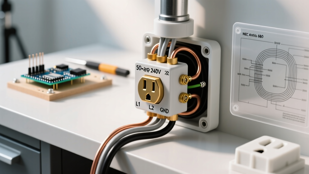

The Anatomy of a 240V Hot Tub Receptacle Setup
Wiring an electrical outlet for hot tub installations is one of the most unforgiving tasks in residential electrical work. The intersection of high-amperage 240V power and large volumes of water demands absolute precision. Unlike standard appliance circuits, a spa circuit must account for continuous water exposure, variable-speed pump harmonics, and strict clearance mandates. This wiring diagram reference and installation guide breaks down the exact specifications, component selections, and code requirements necessary for a safe, inspection-ready 50-amp hot tub outlet.
NEC Article 680: The Non-Negotiable Code Requirements
As of 2026, the vast majority of jurisdictions operate under the 2023 National Electrical Code (NEC) or newer. Article 680 governs swimming pools, fountains, and hot tubs. Two major updates define modern hot tub wiring:
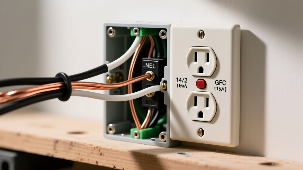
- Mandatory GFCI Protection (NEC 680.42): Every 15- or 20-amp, single-phase, 125-volt or 250-volt receptacle supplying a self-contained spa or hot tub must have Class A Ground-Fault Circuit-Interrupter (GFCI) protection. For 50-amp 240V setups, this means a 2-pole 50-amp GFCI breaker is mandatory at the main panel.
- Emergency Disconnect Updates (NEC 680.12): Historically, an outdoor emergency disconnect switch was required within sight of the hot tub. The 2023 NEC removed this requirement for spas and hot tubs, provided the GFCI breaker is readily accessible and clearly labeled. This saves installers $150 to $300 in outdoor disconnect enclosures, though you must always verify with your local Authority Having Jurisdiction (AHJ), as some municipalities still enforce local amendments.
Expert Insight: Never attempt to wire a hot tub using a standard 2-pole breaker and a GFCI receptacle. The inrush current from spa heaters and multi-speed pumps will instantly degrade standard GFCI receptacles. Protection must originate at the breaker panel.
50-Amp Electrical Outlet for Hot Tub: Wiring Diagram Reference
Modern hot tubs require a 4-wire circuit to accommodate both the 240V heater/pump and the 120V control panel, lights, and ozone generators. Below is the logical wiring flow from the main service panel to the NEMA 14-50R receptacle.
Panel-to-Receptacle Pathway
- Main Panel (Source): The 240V feed enters a 2-pole, 50-amp GFCI breaker (e.g., Square D HOM250GFIC or Siemens Q250GF).
- Neutral Bus Bar: The breaker’s white pigtail wire terminates exclusively on the main panel’s neutral bus bar. Never land this pigtail on the ground bar.
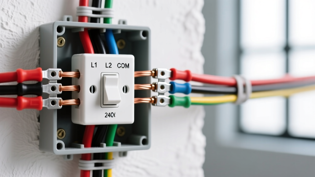
- The 4-Wire Run: Two hot wires (Black, Red), one neutral (White), and one equipment ground (Bare/Green) are pulled through conduit or buried via UF-B cable.
- Receptacle Termination (NEMA 14-50R):
- X Pole (Brass): Black Hot Wire (Line 1)
- Y Pole (Brass): Red Hot Wire (Line 2)
- W Terminal (Silver): White Neutral Wire
- G Terminal (Green): Bare Copper Ground Wire
For a visual representation of standard receptacle wiring and safety protocols, refer to the Safe Electricity outdoor safety guidelines, which emphasize the critical separation of neutral and ground conductors downstream of the main service disconnect.
Component Selection: Breakers, Wire, and Receptacles
Selecting the correct materials prevents voltage drop, nuisance tripping, and catastrophic thermal failures. Use the matrix below to size your components for a 50-amp circuit.
| Component | Specification / Model Example | Installation Notes |
|---|---|---|
| GFCI Breaker | Square D HOM250GFIC (50A, 2-Pole, 120/240V) | Must match panel brand. Expect to pay $110–$160. Requires 1" of neutral bar space for the pigtail. |
| Wire (Conduit) | 6 AWG THWN-2 (Hots/Neutral), 8 AWG Bare (Ground) | Pull through 1" Schedule 80 PVC. THWN-2 is rated for wet locations inside conduit. |
| Wire (Direct Burial) | 6 AWG UF-B (Underground Feeder), 4-Wire | Must be buried at least 24 inches deep. No conduit required for the burial run, but PVC sleeves are needed where the cable emerges above ground. |
| Receptacle | Leviton 278-S00 (NEMA 14-50R, 50A, 125/250V) | Must be paired with a weatherproof "in-use" bubble cover (e.g., TayMac ML500) to maintain code compliance when the spa cord is plugged in. |
Step-by-Step Installation & Termination Sequence
Proper termination is where most DIY installations fail inspection. Follow this sequence to ensure mechanical and electrical integrity.
1. Wire Preparation and Stripping
Strip exactly 5/8" of insulation from the 6 AWG THWN-2 conductors. Use a wire brush to clean the exposed copper if oxidation is present. Apply a thin layer of antioxidant compound (like Noalox) only if you are terminating on aluminum lugs; for copper-to-copper or copper-to-brass, keep the wire clean and dry.
2. Torque Specifications
The NEC (110.14(D)) mandates that all terminations be torqued to the manufacturer’s specifications. For a 50-amp Square D or Siemens breaker utilizing 6 AWG wire, the required torque is typically 40 to 50 inch-pounds. Use a calibrated torque screwdriver. Hand-tightening leads to high-resistance connections that will generate enough heat to melt the breaker housing within 6 months of continuous heater use.
3. Weatherproofing the Receptacle
Mount the NEMA 14-50R receptacle at least 5 feet from the inside wall of the hot tub (NEC 680.43(A)). Seal the conduit entry hub with silicone duct seal to prevent moisture from migrating up the conduit and into the receptacle box. Install the extra-duty in-use cover, ensuring the gasket sits flush against the siding or masonry.
Common Failure Modes & Troubleshooting Nuisance Trips
Even with perfect wiring, hot tub circuits can experience "nuisance tripping" where the GFCI breaker trips without a genuine ground fault. Understanding these failure modes saves hours of diagnostic time.
- Shared Neutrals: If the hot tub's neutral wire accidentally makes contact with a ground wire or another circuit's neutral anywhere downstream of the GFCI breaker, the breaker will trip instantly. The GFCI monitors the current differential between the two hots and the neutral; any leakage to ground triggers the 4-6mA trip threshold.
- Capacitive Coupling on Long Runs: If your wire run exceeds 100 feet, the parallel wires in the conduit can create capacitive coupling, generating a phantom leakage current. Solution: Keep hot, neutral, and ground wires tightly bundled together with wire ties every 3 feet inside the conduit to cancel out electromagnetic fields.
- Moisture Intrusion: If the in-use cover gasket fails, rain or sprinkler water enters the NEMA 14-50R receptacle. Water bridges the gap between the neutral and ground terminals, causing a trip. Solution: Inspect the receptacle annually and apply dielectric grease to the plug prongs.
- Variable Speed Pump Harmonics: Modern hot tubs use VFD (Variable Frequency Drive) pumps that generate electrical noise (harmonics). Older or lower-quality GFCI breakers misinterpret this high-frequency noise as a ground fault. Ensure you are using a modern, microprocessor-equipped GFCI breaker designed for high-inductance loads.
For comprehensive data on electrical safety around water and the physics of ground faults, consult the National Fire Protection Association (NFPA) NEC handbook, as well as the Electrical Safety Foundation International (ESFI) guidelines on outdoor receptacle protection.
Voltage Drop Considerations for Long Runs
A 50-amp 240V circuit operating a 5.5kW spa heater draws approximately 23 amps continuously. According to NEC recommendations, voltage drop should not exceed 3% for branch circuits. Using 6 AWG copper wire, the maximum recommended run length from the panel to the receptacle is 115 feet. If your hot tub is located 150 feet from the main panel, you must upsize your wire to 4 AWG THWN-2 to maintain adequate voltage at the spa controller, preventing premature failure of the heater contactor and control board.
Final Inspection Checklist
Before energizing the circuit, verify the following:
- GFCI breaker pigtail is secured to the neutral bar, not the ground bar.
- All lug screws are torqued to 40-50 in-lbs.
- The receptacle is positioned ≥ 5 feet from the water's edge.
- An extra-duty, in-use weatherproof cover is installed.
- The breaker is clearly labeled "GFCI Protected Hot Tub Receptacle" at the panel directory.