
Decoding the Electrical Three Way Switch Wiring Diagram
Controlling a single light fixture from two separate locations is a staple of residential electrical design, commonly found in stairwells, long hallways, and large living spaces. However, interpreting an electrical three way switch wiring diagram can confuse even seasoned DIYers due to the introduction of 'traveler' wires and varying power source locations. Unlike a standard single-pole switch that simply breaks the hot leg, a 3-way system relies on a continuous loop of alternating paths. In this 2026 guide, we break down the most common wiring scenarios, integrate modern National Electrical Code (NEC) requirements, and provide actionable troubleshooting steps for residential 15-amp and 20-amp lighting circuits.
Safety & Code Warning: Always de-energize the circuit at the main breaker panel and verify zero voltage using a non-contact voltage tester (NCVT) and a multimeter before opening any junction box. According to the National Fire Protection Association (NFPA 70), all residential switch loops must be properly grounded, and new construction requires a neutral conductor at the switch box.
Anatomy of a Standard 3-Way Switch
Before tracing wires through walls, you must understand the physical terminals on the switch body. A standard 3-way switch (such as the Leviton Decora 5603 or Eaton 713W) features three main terminals plus a ground:
- Common Terminal (Black Screw): The pivot point. On the first switch, it connects to the incoming hot power. On the second switch, it connects to the outgoing hot leg feeding the light fixture.
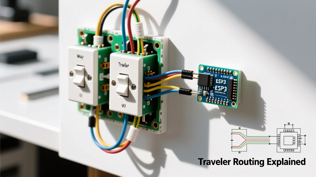
- Traveler Terminals (Two Brass Screws): These carry the alternating current between the two switches. They are interchangeable; swapping them does not affect circuit operation.
- Ground Terminal (Green Screw): Connects to the bare copper or green insulated equipment grounding conductor.
Wire Color Mapping in 3-Wire Cable (NM-B)
| Wire Color | Standard Function in 3-Way Run | NEC Re-identification Rule |
|---|---|---|
| Black | Hot (Line) or Switched Hot (Load) | N/A (Always ungrounded) |
| Red | Traveler 1 | N/A (Always ungrounded) |
| White | Traveler 2 or Neutral | Must be marked with black/red tape if used as a hot/traveler (NEC 200.7(C)) |
| Bare Copper | Equipment Ground | N/A |
Scenario 1: Power Source at the First Switch (The Standard Run)
This is the most intuitive layout and the one most frequently depicted in a standard electrical three way switch wiring diagram. The power from the breaker panel enters Switch Box 1, a 14/3 or 12/3 cable runs between the two switches, and a 14/2 or 12/2 cable runs from Switch Box 2 to the light fixture.
- At Switch Box 1 (Power In): Connect the incoming black (hot) wire to the Common (black) screw. Splice the incoming white (neutral) wire directly to the white neutral wire of the 3-wire cable heading to Switch 2 using a yellow Wing-Nut (rated for three 14 AWG wires). The red and black wires of the 3-wire cable connect to the brass Traveler screws.
- At Switch Box 2 (Power Out to Light): The red and black wires from the incoming 3-wire cable connect to the brass Traveler screws. The white wire of the 3-wire cable (which is acting as the neutral pass-through) is spliced to the white wire of the 2-wire cable heading to the light. The black wire of the 2-wire cable heading to the light connects to the Common (black) screw.
- At the Light Fixture: The black wire from the wall connects to the brass/black hot terminal on the fixture. The white wire connects to the silver/white neutral terminal.
Scenario 2: Power Source at the Light Fixture (The Remodel Challenge)
When power enters at the ceiling box first, the wiring logic shifts. You must route the hot and neutral down to the switches. This requires a 3-wire cable between the light and Switch 1, and another 3-wire cable between Switch 1 and Switch 2.
- At the Light Box: The incoming hot (black) is spliced to the black wire of the 3-wire cable heading down to Switch 1. The incoming neutral (white) is spliced to the white wire of the 3-wire cable heading to Switch 1, and also pigtailed to the light fixture's neutral.
- At Switch Box 1: The black wire from the ceiling is the permanent hot. It connects to the Common screw. The red and white wires of the cable heading to Switch 2 become the travelers. Critical NEC Step: Because the white wire is being used as a traveler (an ungrounded conductor), you must wrap it in black electrical tape at both ends to re-identify it as hot.
- At Switch Box 2: The red and re-identified white (black-taped) wires connect to the Traveler screws. The black wire of the cable coming from Switch 1 connects to the Common screw and acts as the switched hot returning to the light fixture.
2026 Smart Switch Upgrades and NEC 404.2(C)
Upgrading to smart lighting in 2026 requires careful attention to neutral availability. Under NEC Article 404.2(C), new construction and major renovations mandate that a neutral conductor be present at every switch box. This is because smart switches (which contain internal Wi-Fi, Zigbee, or Thread radios) require a complete 120V circuit to power their internal logic boards, even when the light is off.
Top Smart 3-Way Solutions for 2026
| Brand & Model | Protocol | Neutral Required? | Approx. Cost (2026) |
|---|---|---|---|
| Lutron Caséta PD-5S-DV | Clear Connect RF (Thread-ready) | No (Uses patented trickle-current tech) | $65 - $75 |
| Leviton Decora Smart DW3HL | Wi-Fi / Matter | Yes (Strict requirement) | $45 - $55 |
| GE Cync 3-Way Smart Switch | Bluetooth / Wi-Fi | Yes | $35 - $45 |
For homes built before 2011 lacking a neutral at the switch box, the Lutron Caséta system remains the gold standard. Its companion dimmers and switches can operate without a neutral by leaking a tiny current through the LED bulb, though installing their proprietary LUT-MLC capacitor across the fixture's hot and neutral is often required to prevent ghost-flashing in low-wattage LEDs.
Box Fill Calculations: Avoiding Overcrowded Junction Boxes
A frequent mistake when wiring 3-way switches is stuffing too many conductors into a standard builder-grade box. NEC Article 314 dictates strict box fill volumes to prevent wire insulation damage and heat buildup. For standard 14 AWG wire, each conductor counts as 2.0 cubic inches. For 12 AWG, it is 2.25 cubic inches.
Calculation Example (Switch Box 1 with Power In):
- 2 x 14/2 cables (4 current-carrying wires) = 8.0 cu in
- 1 x 14/3 cable (3 current-carrying wires) = 6.0 cu in
- 1 x Switch device (counts as 2 wires) = 4.0 cu in
- 1 x Ground wire (counts as 1 wire) = 2.0 cu in
- Total Required Volume: 20.0 cubic inches. A standard single-gang 'old work' box is only 14-18 cubic inches. You must use a deep single-gang box (22+ cu in) or upgrade to a double-gang box for this scenario.
Troubleshooting Common Wiring Failures
If your light behaves erratically—for example, it only turns on if Switch A is in the 'up' position, but Switch B does nothing—you have a miswired traveler or common terminal. The U.S. Consumer Product Safety Commission (CPSC) advises against relying on trial-and-error toggling, which can arc and degrade switch contacts. Instead, use a multimeter set to continuity (the beep mode).
- Identify the Common: With power OFF and wires disconnected, place one probe on the black (common) screw and the other on a brass traveler. Flip the toggle. The multimeter should beep on one throw, and go silent on the other. Repeat for the second brass screw. The screw that alternates continuity is your verified Common.
- Check for Switched Neutrals: A dangerous and code-violating mistake is switching the neutral instead of the hot leg. This leaves the light fixture energized at 120V even when the light is off, posing a severe shock hazard during bulb changes. Always verify that the white wire in the switch box is a true neutral (0V to ground) using a multimeter before finalizing connections.
- LED Ghosting: If your LEDs glow faintly when the 3-way switch is off, you likely have an illuminated locator switch (a switch with a built-in neon nightlight). The neon light requires a tiny current loop that passes through the LED driver. Swap to a standard non-illuminated 3-way switch or install a bypass resistor at the fixture.
Frequently Asked Questions
Can I use a 4-way switch in a 3-way diagram?
No. A 4-way switch has four traveler terminals and no common terminal. It is designed exclusively to be placed between two 3-way switches to allow control from three or more locations. Installing it at the end of a run will result in a dead circuit.
Does it matter which traveler wire goes to which brass screw?
Electrically, no. The brass screws are symmetrical in their function. However, for future troubleshooting and maintaining a clean electrical three way switch wiring diagram, it is best practice to keep the red wire on the top brass screw and the black (or re-identified white) on the bottom brass screw consistently across both switches.