
Understanding the Electric Shock Outlet Phenomenon
Feeling a tingling sensation or a sharp jolt when touching an appliance plugged into a wall receptacle, or even grazing the metal screws of the faceplate, is a severe safety hazard. An electric shock outlet issue typically indicates a missing equipment grounding conductor (EGC), reversed polarity, a 'bootleg' ground, or a degraded internal connection causing current to leak onto exposed metal surfaces. According to the Electrical Safety Foundation International (ESFI), ground faults and improper wiring are responsible for hundreds of fatal electrocutions and thousands of severe injuries annually in residential settings.
As a DIYer or homeowner, you cannot simply ignore a shocking outlet or cover it with tape. The National Electrical Code (NEC) mandates specific remediation steps. In this comprehensive guide, we will walk through the exact diagnostic procedures and the step-by-step installation of a Ground Fault Circuit Interrupter (GFCI) to permanently neutralize the shock hazard and bring your circuit up to modern 2026 safety standards.
Pre-Installation Diagnostics: Identifying the Root Cause
Before ripping the old receptacle out of the wall, you must understand why the shock is occurring. Grab a reliable receptacle tester, such as the Gardner Bender GFI-3511 (approx. $12), and a True-RMS digital multimeter like the Klein Tools MM400 (approx. $45).
Testing for Voltage Leaks and Bootleg Grounds
- The Bootleg Ground: This is a dangerous, illegal wiring trick where a jumper wire connects the neutral terminal to the ground terminal on a standard duplex receptacle. It fools a basic 3-light tester into showing 'correct wiring,' but if the neutral wire ever lifts or carries heavy current, the ground path (and anything plugged into it) becomes energized at 120V. To check for this, turn off the breaker, remove the faceplate, and look for a jumper wire between the silver (neutral) and green (ground) screws.
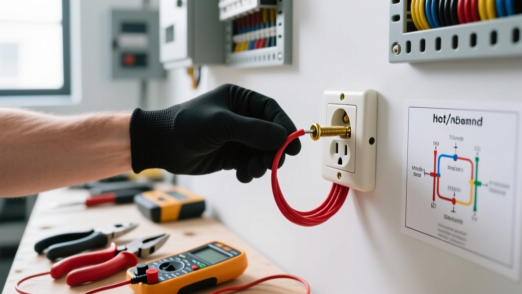
- Induced Voltage vs. Real Fault: Set your multimeter to AC Voltage. Place the red probe on the metal faceplate screw and the black probe on a known good ground (like a copper water pipe or the grounding slot of a verified receptacle). A reading under 2V is usually harmless induced phantom voltage. A reading above 40V indicates a severe insulation failure or a missing EGC combined with a ground fault.
Step-by-Step Installation: Upgrading to a GFCI Receptacle
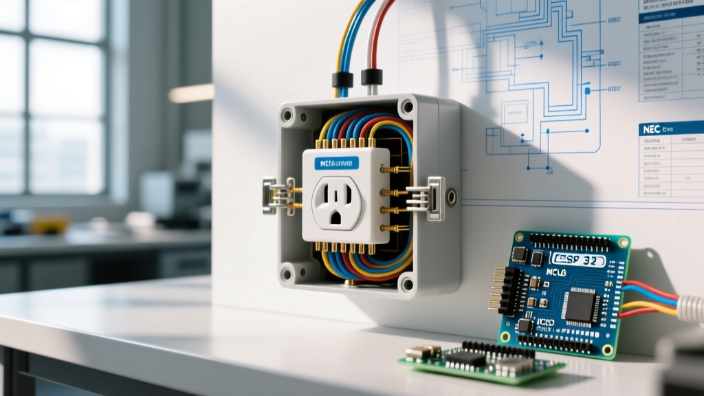
If your testing reveals an ungrounded circuit or a persistent fault, NEC Article 406.4(D)(4) permits you to replace the faulty, ungrounded receptacle with a GFCI. This provides personnel protection against lethal shocks, even without a physical ground wire. We will use the Leviton SmartlockPro 15A GFCI (Model 1599-SW1), which retails for roughly $22 to $28 and features advanced internal diagnostics.
Step 1: Lockout, Tagout, and Verify
Turn off the circuit breaker at the main panel. Do not rely solely on a wall switch. Use a non-contact voltage tester (NCVT) to scan the top and bottom slots of the receptacle. Then, insert your multimeter probes into the hot and neutral slots to confirm 0.0V.
Step 2: Extract and Inspect the Wiring
Remove the center mounting screw and pull the receptacle from the gang box. Inspect the wire insulation. If you see melted, blackened, or brittle thermoplastic insulation, the circuit has been overheating. You must strip back the damaged wire to fresh, clean copper using a wire stripper. If the damage extends deep into the Romex sheathing, you may need to replace the entire cable run.
Step 3: Prep the Conductors (Strip Gauge Precision)
Look at the back of the Leviton GFCI. You will see a physical strip gauge molded into the plastic. For 14 AWG and 12 AWG solid copper wire, strip exactly 5/8 inch of insulation. Stripping too little results in the insulation being clamped under the terminal plate, causing a high-resistance open circuit. Stripping too much leaves exposed, uninsulated copper inside the box, creating an arc flash hazard.
Step 4: LINE vs. LOAD Termination
This is where most DIYers fail. A GFCI has two distinct sets of terminals:
- LINE Terminals: These connect to the incoming power from the breaker panel. The black (hot) wire goes to the brass LINE screw, and the white (neutral) wire goes to the silver LINE screw.
- LOAD Terminals: These connect to downstream outlets, extending GFCI protection to other receptacles in the room. If you are only protecting this single outlet, use the LINE terminals exclusively and cap the LOAD terminals with the included yellow warning tape.
Pro-Tip: Utilize the back-wiring pressure plates rather than side-wiring the screws. Back-wiring provides a superior, uniform clamping force that prevents the wire from slipping out over time due to thermal expansion and contraction.
Step 5: Torque and Mount
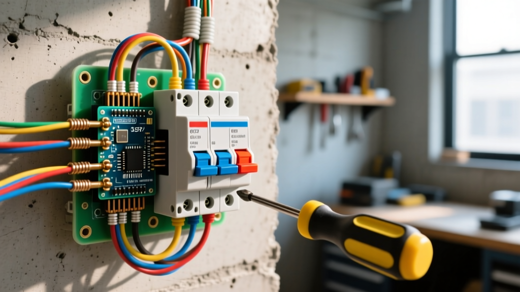
Using a calibrated torque screwdriver (such as the Klein Tools 695), tighten the terminal screws to 14 in-lbs. This specific torque ensures the brass threads are not stripped and the copper wire is not deformed, which could lead to a high-resistance connection and subsequent heat buildup. Carefully fold the wires in a Z-pattern into the back of the gang box, mount the GFCI using the provided 6-32 mounting screws, and attach the faceplate.
Common Wiring Faults That Cause Shocks (And How to Fix Them)
Understanding the specific electrical fault helps you apply the correct installation fix. Refer to the matrix below for quick troubleshooting.
| Fault Condition | Symptom / Multimeter Reading | Required Installation Fix |
|---|---|---|
| Open Equipment Ground | 120V reading from Hot to Ground slot; 0V from Neutral to Ground. | Install GFCI on LINE terminals. Label receptacle 'No Equipment Ground' per NEC 406.4(D)(4). |
| Reversed Polarity | Shock on appliance chassis; Tester shows 'Hot/Neutral Reversed'. | Swap the black and white wires on the LINE terminals. Verify with NCVT. |
| Bootleg Ground Jumper | Tester shows 'Correct', but shock occurs under load. | Remove jumper wire immediately. Wire GFCI correctly and apply warning sticker. |
| Degraded Insulation | Intermittent shocks; breaker trips randomly. | Strip back damaged Romex sheathing; replace cable if damage is extensive. |
Advanced Edge Cases: Multi-Wire Branch Circuits (MWBC)
If you open the gang box and find two black wires, two white wires, and a single red wire, you are dealing with a Multi-Wire Branch Circuit (MWBC). MWBCs share a single neutral wire across two separate hot phases (L1 and L2) to save copper.
Attempting to wire a standard GFCI on the LOAD side of an MWBC without separating the neutrals will cause the GFCI's internal sensing coil to detect an imbalance and immediately trip the moment a load is applied. Furthermore, if the shared neutral is disconnected while the circuit is live, the return current will backfeed through the appliance, creating a lethal shock hazard on the neutral bus.
'GFCI devices monitor the current balance between the ungrounded (hot) and grounded (neutral) conductors. Any modification to the neutral path, such as sharing it downstream of the GFCI LOAD terminals, will result in nuisance tripping or failure to protect.' — National Fire Protection Association (NFPA) NEC Guidelines
The Fix: You must pigtail the incoming neutral wires. Connect the two incoming white wires together with a wire nut and a 6-inch white pigtail. Connect the pigtail to the LINE neutral terminal of the GFCI. Do not use the LOAD terminals for downstream MWBC receptacles; instead, install separate GFCIs at each downstream location or use a 2-pole GFCI breaker in the main panel.
Final Testing and Safety Verification
Once the GFCI is installed and the power is restored, press the 'TEST' button on the receptacle. The 'RESET' button should pop out with an audible click, and the LED indicator (if equipped) should change state. Plug in a lamp to verify that downstream LOAD receptacles (if wired) are also dead. Finally, use your 3-light tester to confirm the GFCI trips correctly when you press the tester's black button.
By systematically diagnosing the root cause and executing a precision GFCI installation, you eliminate the electric shock outlet hazard entirely. Always adhere to local electrical codes and consult a licensed electrician if you encounter aluminum wiring, extensive thermal damage, or panels lacking adequate space for AFCI/GFCI breakers. For further reading on workplace and residential electrical safety protocols, review the OSHA Electrical Safety Guide.