
Decoding the Standard Diagram for Electrical Outlet Wiring
Understanding a proper diagram for electrical outlet wiring is the foundational skill for any DIYer or apprentice electrician. Whether you are replacing a damaged receptacle in a 1970s kitchen or running a new branch circuit for a home office in 2026, the physical layout of the terminals remains governed by strict National Electrical Code (NEC) standards. A wiring diagram is not just a suggestion; it is a visual map that ensures polarity, grounding continuity, and overcurrent protection are correctly maintained. In this guide, we will break down the anatomy of a standard 120-volt duplex outlet diagram and provide a meticulous, step-by-step installation procedure that aligns with modern safety codes.
Anatomy of the Outlet Diagram: Terminals and Color Codes
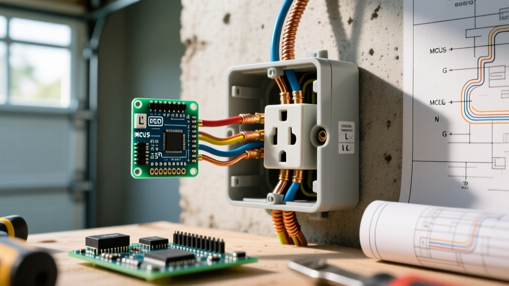
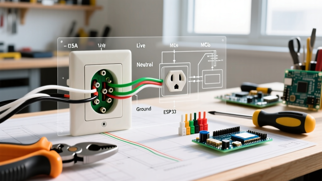
Before picking up a screwdriver, you must be able to translate the schematic diagram into the physical brass, silver, and green screws on your receptacle. A standard diagram for electrical outlet wiring highlights three critical connection points:
- Brass Terminals (Hot/Line): These connect to the black (or sometimes red) insulated wire. This is the ungrounded conductor carrying 120V from the breaker panel. The brass screws are typically connected to the shorter slot on the face of the receptacle.
- Silver Terminals (Neutral): These connect to the white insulated wire. This is the grounded conductor that completes the circuit back to the panel. The silver screws align with the longer slot on the receptacle face.
- Green Terminal (Ground): This connects to the bare copper or green insulated wire. It provides a safe path for fault currents, tripping the breaker in the event of a short circuit.
Pro-Tip for 2026 Code Compliance: Under recent NEC updates (specifically NEC 406.4(D)), if you are replacing an outlet in a location that now requires GFCI or AFCI protection (like kitchens, bathrooms, or bedrooms), you cannot simply install a standard receptacle. You must either install a GFCI receptacle or ensure the circuit is protected at the breaker level. Always consult your local Authority Having Jurisdiction (AHJ) before upgrading.
Required Tools and Materials
Professional results require professional tools. Do not rely on a dull utility knife or a cheap multi-bit screwdriver. Here is the exact loadout required for a safe, code-compliant installation:
- Wire Strippers: Klein Tools 11063W (10-14 AWG) for precise insulation removal without nicking the copper.
- Torque Screwdriver: Milwaukee 48-22-2601 or similar, calibrated to 14 in-lbs. (The National Fire Protection Association (NFPA) and UL 498 standards mandate specific torque values to prevent loose connections and arc faults).
- Non-Contact Voltage Tester: Milwaukee 2202-20 or Fluke 1AC-II to verify the circuit is dead.
- Receptacle: Leviton 5362 (15A Commercial Grade) or Eaton TRCR15W (Tamper Resistant). Always use Tamper Resistant (TR) models for residential spaces.
- Wire Connectors: 3M Scotchlok or Ideal Wire-Nuts (yellow or red, depending on gauge).
Step-by-Step Installation Guide
Step 1: De-energize and Verify
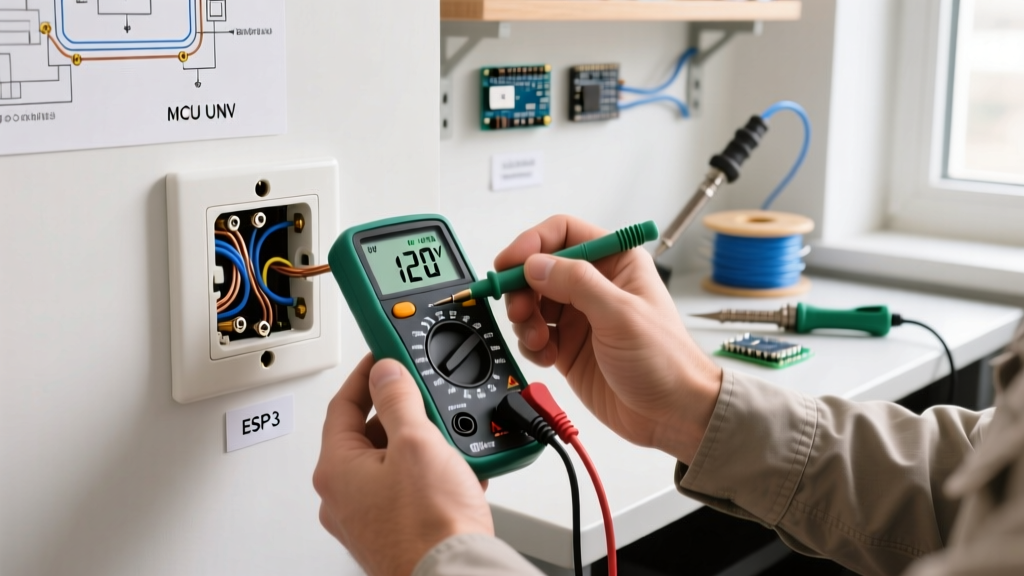
Safety is non-negotiable. According to OSHA electrical safety guidelines, working on live circuits is a leading cause of residential and commercial electrical fatalities. Turn off the corresponding 15A or 20A breaker at the main panel. Use your non-contact voltage tester on the existing outlet's slots and the wires inside the box. Test the tester on a known live circuit first to ensure the battery is functioning.
Step 2: Prep the Wires to Exact Measurements
A common failure point in DIY wiring is improper stripping. If you strip too little insulation, the screw head will bite into the plastic, causing high resistance and heat. If you strip too much, exposed copper will sit outside the terminal, creating a shock hazard.
- Use the built-in stripping gauge on your wire strippers. For 14 AWG and 12 AWG solid copper wire, strip exactly 3/4 inch of insulation.
- Inspect the exposed copper. If it is deeply scored or nicked by the stripping holes, cut it back and strip again. A nicked wire will snap when bent and can cause an arc fault inside the wall.
- Use needle-nose pliers to form a smooth, clockwise 'J-hook' or 'Shepherd's hook' at the end of the wire. Modern commercial-grade receptacles with deep-wire clamps allow for straight insertion, but standard side-wiring requires the hook.
Step 3: Execute the Wiring Diagram Connections
Following your diagram for electrical outlet wiring, make the connections in this specific order to maintain organization and safety:
- Ground First: Loop the bare copper wire clockwise around the green grounding screw. Tighten using your torque screwdriver set to 14 in-lbs. If you are daisy-chaining outlets, you must pigtail the ground wires together with a wire nut and a 6-inch pigtail to the receptacle. Never break the ground path.
- Neutral Second: Connect the white wire to the silver screw. Again, use the clockwise hook so the tightening motion pulls the wire tighter rather than pushing it out. For Multi-Wire Branch Circuits (MWBC), NEC 300.13(B) strictly requires pigtailing the neutral so removing the receptacle does not break the neutral for the other half of the circuit.
- Hot Last: Connect the black wire to the brass screw. Ensure no bare copper is visible outside the terminal plate.
Step 4: Box Make-Up and Mounting
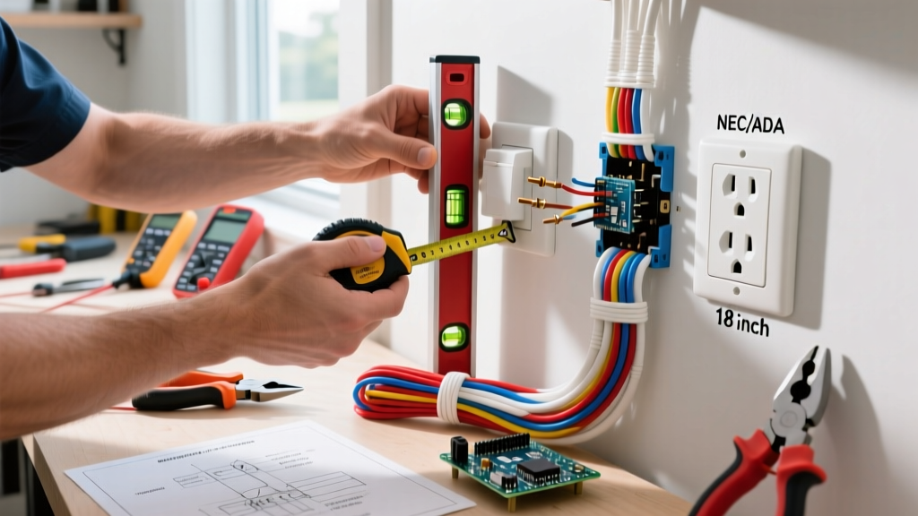
Carefully fold the wires into the back of the electrical box. The 'accordion fold' method works best: push the ground wire deep into the back, followed by the neutral wires, and finally the hot wires. This keeps the hot wires furthest from the metal box (if applicable) and prevents pinching. Mount the receptacle using the provided 6-32 mounting screws. Use a torpedo level to ensure the strap is perfectly plumb before tightening.
Standard vs. GFCI Outlet Diagram Comparison
While a standard outlet diagram is straightforward, upgrading to a Ground Fault Circuit Interrupter (GFCI) introduces complexity. The U.S. Consumer Product Safety Commission (CPSC) strongly recommends GFCI protection in all wet or damp locations. Below is a structural comparison of how the diagrams differ:
| Feature | Standard Duplex Outlet | GFCI Receptacle |
|---|---|---|
| Terminal Types | Brass (Hot), Silver (Neutral), Green (Ground) | LINE (Hot/Neutral), LOAD (Hot/Neutral), Green (Ground) |
| Downstream Protection | None. Downstream outlets are unprotected. | Wiring to LOAD terminals protects downstream outlets. |
| Wiring Complexity | Low. Simple point-to-point connection. | High. Must correctly identify line vs. load source. |
| Physical Depth | Approx. 1.1 inches (fits easily in standard boxes). | Approx. 1.6 to 2.0 inches (requires deep 48 cu. in. boxes). |
| Cost (2026 Avg) | $3.50 - $5.00 per unit | $18.00 - $28.00 per unit |
Common Wiring Mistakes and Edge Cases
Even with a clear diagram for electrical outlet wiring, errors occur. Here are the most frequent edge cases and how to troubleshoot them:
- Reverse Polarity: Swapping the black and white wires. The outlet will still power a lamp, but the internal switch of the appliance will interrupt the neutral instead of the hot wire, leaving the appliance energized internally. This is easily caught by a $12 Klein Tools RT250 GFCI receptacle tester.
- Bootleg Grounds: A dangerous, illegal practice where a jumper wire is installed between the neutral (silver) terminal and the ground (green) screw to trick a tester into showing a 'correct' wiring reading. If a neutral fault occurs upstream, the metal casing of any plugged-in appliance becomes fully energized at 120V.
- Back-Stabbing: Pushing stripped wires into the quick-insert holes on the back of the receptacle. While technically legal on some 15A models, the internal spring-loaded contacts degrade over time, leading to high-resistance connections and melted plastic. Always use the side terminal screws or the screw-clamp back-wiring plates found on commercial-grade (Spec-Grade) receptacles.
- Over-torquing: Using an impact driver or overtightening with a standard screwdriver can strip the brass threads or crack the thermoplastic housing of the receptacle, compromising its UL listing. Stick to the 14 in-lbs specification.
Final Inspection and Testing
Once the cover plate is installed and the breaker is turned back on, do not assume the job is complete. Insert a digital receptacle tester into the top and bottom sockets. The indicator lights should display 'Correct Wiring' (usually two yellow lights, depending on the brand). Press the GFCI test button if applicable. If the breaker trips or the tester shows an open ground, turn the power back off immediately, remove the cover plate, and re-verify your torque and wire seating against your original diagram.
Mastering the diagram for electrical outlet wiring transforms a daunting task into a predictable, safe, and highly rewarding process. By respecting the color codes, adhering to torque specifications, and understanding the 'why' behind the NEC requirements, you ensure your home's electrical infrastructure remains safe for decades to come.