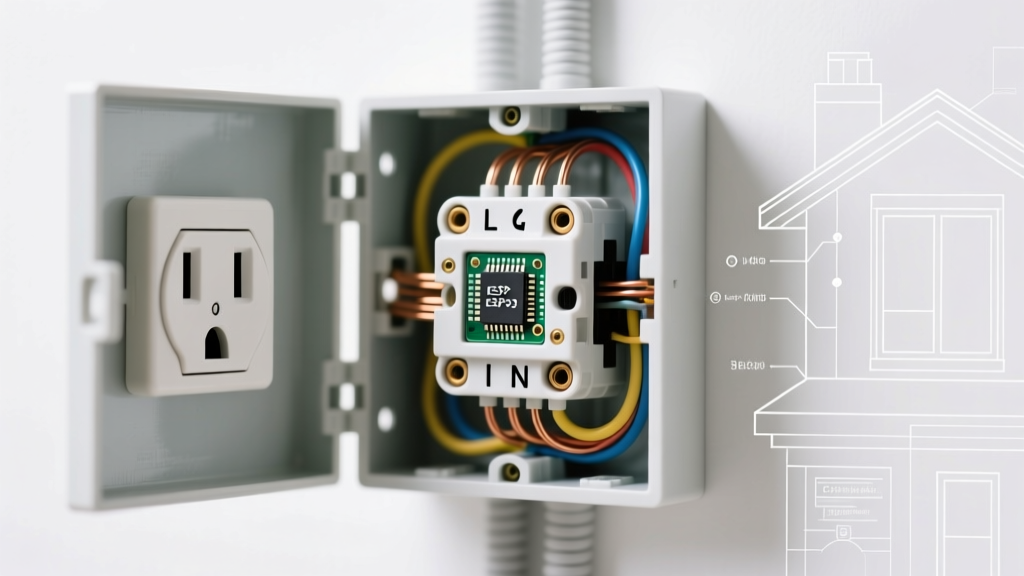

The Critical Role of GFCI Wiring in Modern Electrical Safety
Ground Fault Circuit Interrupters (GFCIs) are the undisputed frontline defense against lethal electrocution in residential and commercial environments. According to the U.S. Consumer Product Safety Commission (CPSC), the widespread adoption of GFCI technology has reduced residential electrocutions by over 80% since the 1970s. However, simply installing the device is not enough; interpreting and executing the correct wiring diagram for GFCI receptacles is where true safety and code compliance are achieved. A misunderstood terminal connection can leave downstream circuits entirely unprotected while giving the false illusion of safety.
This guide dissects the standard wiring diagram for GFCI outlets through the lens of the latest National Electrical Code (NEC) requirements, highlighting specific failure modes, torque specifications, and edge cases that separate amateur DIY attempts from professional, inspector-approved installations.
Decoding the Standard Wiring Diagram for GFCI Receptacles
Unlike standard duplex receptacles that simply pass current through via brass and silver terminal strips, a GFCI receptacle contains an internal current transformer (CT). This CT continuously monitors the vector sum of the current flowing through the ungrounded (hot) and grounded (neutral) conductors. If a differential as small as 5mA (± 1mA) is detected—indicating current is leaking to ground, potentially through a human body—the internal solenoid trips the contacts in under 25 milliseconds.
The Line vs. Load Distinction
The most common point of failure when following a wiring diagram for GFCI devices is confusing the LINE and LOAD terminals. Modern 15A and 20A Tamper-Resistant (TR) GFCIs, such as the Leviton T5325-W or Hubbell GF5252W (typically retailing between $16 and $24), clearly label these terminals on the rear strap.
| Terminal Type | Function | Connection Source | Code Implication |
|---|---|---|---|
| LINE | Receives incoming power from the breaker panel. | Feed wires from the branch circuit. | Must be correctly identified to power the GFCI's internal sensing circuitry. |
| LOAD | Sends protected power to downstream standard receptacles. | Wires continuing to the next outlet in the daisy chain. | NEC requires downstream protection in specific zones; miswiring here voids protection. |
| GROUND | Provides a low-impedance fault path. | Bare copper or green insulated wire. | GFCIs function without a ground, but NEC mandates an equipment grounding conductor (EGC) for new installations. |
Reverse Line/Load Protection (UL 943 Compliance)
Historically, if an electrician reversed the line and load connections, the GFCI would still power the receptacle and even trip when the test button was pressed, but it would fail to protect downstream devices. Under the revised UL 943 standard, modern GFCIs feature reverse line/load protection. If wired backward, the internal circuitry physically prevents the reset button from engaging. While this is a massive safety upgrade, it frequently results in confused callbacks for installers who fail to identify the incoming feed before terminating wires.
NEC Code Compliance: Where GFCIs Are Mandated
The National Fire Protection Association (NFPA) 70, or NEC, continually expands GFCI requirements based on field data and failure analysis. When reviewing your wiring diagram for GFCI placement, you must adhere to Article 210.8. Recent code cycles have drastically expanded the scope of required protection.
- Residential (210.8(A)): Bathrooms, garages, accessory buildings, outdoors, crawlspaces, basements, kitchens (countertop receptacles), laundry areas, and within 6 feet of sinks, bathtubs, or shower stalls.
- Non-Residential (210.8(B)): Similar wet/damp locations, plus indoor areas with concrete floors (like warehouses) where personnel may be grounded.
- The 250V Expansion: A critical update in recent NEC cycles mandates GFCI protection for all 125-volt through 250-volt receptacles rated 150 volts or less to ground, up to 50 amperes, in the locations listed above. This means your 240V garage receptacles (e.g., NEMA 14-50 for EV chargers or welders) now require GFCI protection, fundamentally altering the wiring diagrams for high-voltage residential circuits.
Advanced Edge Case: Multi-Wire Branch Circuits (MWBC)
One of the most severe edge cases that ruins a standard wiring diagram for GFCI installations is the Multi-Wire Branch Circuit (MWBC). An MWBC uses two ungrounded conductors (hot wires on opposite phases) sharing a single grounded conductor (neutral).
Expert Warning: You cannot wire the LOAD side of a standard single-pole GFCI to protect downstream receptacles on an MWBC if the neutral is shared. The GFCI's internal CT will read the unbalanced return current from the second hot leg as a ground fault, causing immediate, un-resettable nuisance tripping.
The Compliant Solution: If you must provide GFCI protection on an MWBC, you have two code-compliant options: 1. Install a 2-pole GFCI circuit breaker in the panel, which monitors both hot legs and the shared neutral simultaneously. 2. Pigtail the neutrals in the junction box so that each GFCI receptacle only monitors the neutral current associated with its specific hot leg, keeping the shared neutral strictly on the LINE side or upstream of the GFCI.
Termination, Torque, and Installation Specifics
Following the diagram is only half the battle; the physical execution must meet OSHA and NEC Article 110.14(D) standards for mechanical and electrical integrity. Loose connections cause arcing, heat buildup, and premature failure of the GFCI's sensitive electronics.
- Wire Stripping: Use the built-in gauge on the back of the GFCI. For 12 AWG and 14 AWG solid copper wire, the strip length is typically 5/8 inch. Exposed copper beyond the terminal pad is a shock hazard and a code violation.
- Terminal Selection: Always use the screw terminals or the internal pressure clamps (back-wiring) for LINE and LOAD connections. Never use the push-in stab connections on the back of the device for high-load circuits; they are prone to loosening over time due to thermal cycling.
- Torque Application: NEC 110.14(D) requires terminals to be tightened to the manufacturer's specified torque using a calibrated tool. For example, Leviton specifies 14 in-lbs for their ProSpec GFCI terminal screws. Use a calibrated torque screwdriver (such as the Klein Tools 32308) to ensure exact compliance and prevent stripped threads or crushed conductors.
Testing and Commissioning: Verifying the Diagram
Once the wiring diagram for GFCI connections is executed and the device is powered, commissioning must occur. Do not rely solely on the receptacle's built-in "TEST" button. The internal test button merely injects a small current bypass around the CT to verify the solenoid works; it does not verify that the physical wiring to the LINE and LOAD terminals is correct.
Instead, use an external solenoid-based GFCI tester, such as the Klein Tools RT210. When plugged into the receptacle, this device creates an actual 6mA ground fault from the hot conductor to the equipment grounding conductor. If the GFCI trips, you have verified both the internal mechanism and the integrity of the physical wiring path. Furthermore, test all downstream receptacles connected to the LOAD terminals to ensure the feed-through protection is active.
Final Safety Takeaway
Mastering the wiring diagram for GFCI devices requires more than matching colors to screws. It demands a rigorous understanding of current vectors, NEC zone expansions, and torque specifications. By treating every installation with the precision of a life-safety system, you ensure compliance, pass inspections on the first attempt, and most importantly, protect the end-users from fatal electrical hazards.