
Understanding the SAE J286 Standard 7-Way Blade Connector
When transitioning from standard household electrical receptacles to automotive and RV wiring, the 7-way RV blade connector is the most critical junction you will encounter. Governed by the SAE J286 standard, this connector bridges the tow vehicle and the trailer, handling everything from basic illumination to high-current electric braking systems. For beginners, interpreting a wiring diagram for 7 pin trailer plug configurations can be daunting due to inconsistent aftermarket color coding and varying wire gauge requirements.
Unlike a standard NEMA 5-15 wall outlet where hot, neutral, and ground are rigidly defined by the National Electrical Code (NEC), trailer wiring relies on functional circuits that share grounds and combine turn signals with brake lights. A failure in this junction doesn't just trip a breaker; it can result in total brake loss on a 10,000-pound toy hauler or cause a short circuit that melts the vehicle's harness. This guide provides a precise, field-tested approach to wiring, terminating, and sealing a 7-pin plug, utilizing 2026 industry-standard materials and practices.
The Universal Wiring Diagram for 7 Pin Trailer Plug Pinouts
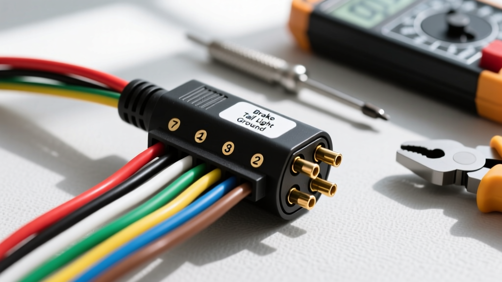
The physical layout of the 7-pin connector is standardized, but the wire colors feeding the back of the plug are notoriously unreliable in the real world. While the etrailer wiring FAQ database outlines standard factory colors, you must always verify the function with a digital multimeter before crimping. Below is the definitive matrix for the SAE J286 pinout.
| Pin Position | Function | Standard Wire Color | Minimum Wire Gauge | Max Amperage Draw |
|---|---|---|---|---|
| 1 (Ground) | Chassis Ground | White | 8 AWG | N/A (Return Path) |
| 2 | Tail / Running Lights | Brown | 12 AWG | 10A |
| 3 | Left Turn / Brake | Yellow | 12 AWG | 10A |
| 4 | Right Turn / Brake | Green | 12 AWG | 10A |
| 5 | Electric Brakes | Blue | 10 AWG | 12A - 15A |
| 6 | 12V Auxiliary Power | Black | 10 AWG | 20A - 30A |
| 7 | Reverse / Auxiliary | Red or Purple | 12 AWG | 10A |
Expert Warning: Never rely solely on wire color to identify circuits. Previous owners, cheap aftermarket adapters, and proprietary OEM harnesses frequently deviate from SAE standards. Always back-probe the vehicle-side receptacle with a multimeter to confirm the active pin before terminating the trailer side.
2026 Tool & Material Checklist for Beginners
To ensure a weatherproof and voltage-drop-free connection, you need the right materials. Standard big-box store electrical tape and wire nuts will fail within weeks due to UV exposure and vibration. Budget approximately $65 to $90 for professional-grade consumables.
- Connector Housing: Curt 58150 7-Way RV Blade Connector with heavy-duty strain relief boot (Approx. $18.50).
- Wire: Ancor Marine Grade Tinned Copper Wire. Tinned copper resists galvanic corrosion inside the plug housing. Use 10 AWG for brakes/power and 12 AWG for lighting ($35 for a 50ft spool).
- Terminals: Heat-shrink ring terminals, sized #10 stud for the plug's internal screws. Avoid spade terminals; they vibrate loose under highway conditions.
- Sealant: Permatex 22058 Dielectric Tune-Up Grease ($6.98). This prevents moisture ingress and stops copper oxidation without impeding conductivity.
- Tools: Klein Tools 11063W wire strippers, a ratcheting terminal crimper (like the IWISS IWS-10), and a basic digital multimeter.
Step-by-Step Installation Flow
Follow this exact sequence to avoid the most common beginner mistake: stripping and crimping the wires before feeding them through the housing boot.
Step 1: Route the Cable and Prepare the Housing
Unscrew the faceplate of the 7-pin plug. Slide the main trailer cable through the rubber strain relief boot and the rear housing shell before stripping any insulation. Leave at least 8 inches of working length inside the housing. If your cable jacket is thick, use a utility knife to carefully slit and remove 3 inches of the outer jacket, exposing the individual colored wires.
Step 2: Strip, Crimp, and Heat-Shrink
Strip exactly 3/8" of insulation from each wire. Slide a piece of adhesive-lined marine heat shrink over each wire. Crimp the #10 ring terminal using a ratcheting crimper to ensure a uniform, gas-tight compression. Slide the heat shrink over the crimp barrel and apply heat until the inner adhesive oozes out, creating a waterproof seal.
Step 3: Terminate to the Pinout Matrix
Refer to the wiring diagram for 7 pin trailer plug matrices above. Loosen the terminal screws on the plug insert. Slide the ring terminals over the screws and tighten them securely.
Pro-Tip: Apply a small dab of Permatex dielectric grease to the threads of each screw before tightening. This prevents galvanic corrosion between the brass screw and the copper terminal, a primary cause of voltage drop in older trailers.
Step 4: Seal and Reassemble
Once all seven wires are secured, gently fold the excess wire into the rear cavity. Do not pinch the wires against the sharp edges of the housing. Slide the rubber strain relief boot up to the cable jacket and secure it using a stainless-steel hose clamp or heavy-duty zip tie. Screw the faceplate back on, ensuring the internal rubber gasket is perfectly seated.
Critical Failure Modes and Edge Cases
Even with a perfect wiring diagram for 7 pin trailer plug setups, physical installation errors can cause cascading electrical failures. Here are the most common edge cases encountered in the field:
The Ground Wire Bottleneck (Voltage Drop)
Pin 1 (White) is the ground for the entire lighting circuit. If you use 12 AWG wire for the ground, the combined resistance of the tail lights, marker lights, and brake lights will cause a voltage drop. This manifests as dim lights or a phenomenon called "ghosting," where applying the brakes causes the running lights to flicker. Always use 8 AWG or even 6 AWG wire for the ground pin, especially on trailers over 20 feet in length.
Electric Brake Current Surges
Pin 5 (Blue) feeds the electric brake magnets. A dual-axle trailer draws roughly 8 to 10 amps, while a triple-axle toy hauler can pull 15 amps continuously during a hard downhill stop. Using 12 AWG wire here will cause the wire to heat up, melting the internal plastic housing of the plug. Stick strictly to 10 AWG minimum, and ensure your tow vehicle's brake controller is rated for the specific axle count.
12V Auxiliary Overloading
Pin 6 (Black) provides 12V power from the tow vehicle's alternator to charge the trailer's breakaway battery or power interior RV lights. Many beginners wire a 2000W inverter directly to this pin. This will instantly melt the harness. The 12V auxiliary pin is typically fused at 30A or 40A at the tow vehicle's fuse box. It is strictly for battery trickle charging and low-draw accessories. For high-draw inverters, you must install a dedicated Anderson Powerpole connector bypassing the 7-pin entirely.
Frequently Asked Questions
Why do my trailer brakes lock up when I plug in the 7-pin connector?
This is almost always caused by a short circuit between Pin 5 (Electric Brakes) and Pin 6 (12V Auxiliary). If the 12V hot wire touches the brake wire inside the plug housing due to poor insulation or a loose terminal, the brake controller will receive 12V continuously, locking the brakes. Disconnect immediately, open the plug, and inspect for crossed terminals.
Can I use a 4-pin to 7-pin adapter instead of rewiring?
Yes, for lightweight utility trailers without electric brakes or auxiliary power needs. However, adapters introduce an additional point of failure and moisture ingress. For travel trailers and car haulers, hardwiring a dedicated 7-pin plug using the proper wiring diagram is the only safe, reliable method. For more on adapter limitations, refer to the Hopkins Towing Solutions support documentation.
How do I test the wiring without a tow vehicle?
You can use a 12V automotive battery and a set of fused jumper wires. Connect the battery's negative terminal to Pin 1 (Ground). Briefly tap the positive terminal to Pins 2, 3, 4, and 7 to verify the corresponding lighting circuits. Never tap Pin 5 (Brakes) or Pin 6 (Aux) without an inline 15A fuse on your jumper wire to prevent a dead short if the trailer wiring is compromised.
By treating your trailer's electrical junction with the same respect and precision as a home electrical panel, you ensure safe, legal, and hassle-free towing. Always double-check your pinouts, oversize your ground wire, and seal every connection against the elements.