
Why Stove Outlet Wiring Demands Rigorous Inspection
Modern electric ranges and dual-fuel stoves are among the most power-hungry appliances in a residential setting, frequently drawing between 40 and 50 amps at 240 volts. When evaluating the electrical wiring for stove outlet configurations, inspectors and DIYers must look beyond simple functionality. A poorly terminated 50-amp NEMA 14-50R receptacle can generate enough resistive heat to melt the faceplate, degrade wire insulation, and ultimately trigger an electrical fire.
According to the National Fire Protection Association (NFPA), electrical distribution and lighting equipment account for a significant percentage of home structural fires. Because stove circuits operate continuously under high thermal loads, verifying the integrity of the electrical wiring for stove outlet connections is a critical safety mandate, not just a code formality.
Essential Tools for 240V Receptacle Testing
Before approaching the panel or the receptacle, assemble professional-grade testing equipment. Standard 120V plug-in testers are useless for 240V/50A circuits.
- Digital Multimeter (DMM): A CAT III 600V or CAT IV 600V rated meter is mandatory. The Fluke 117 (approx. $200) or Klein Tools MM700 (approx. $90) are excellent choices for true-RMS voltage readings.
- Calibrated Torque Screwdriver: The CDI 1002TFRMHSS (approx. $130) or a similar preset torque driver capable of measuring 30 to 50 inch-pounds.
- Infrared Thermometer: A tool like the Fluke 62 MAX+ (approx. $120) for non-contact thermal scanning under load.
- Non-Contact Voltage Tester (NCVT): For initial dead-circuit verification before removing the receptacle cover.
Phase 1: Visual and Mechanical Inspection (De-Energized)
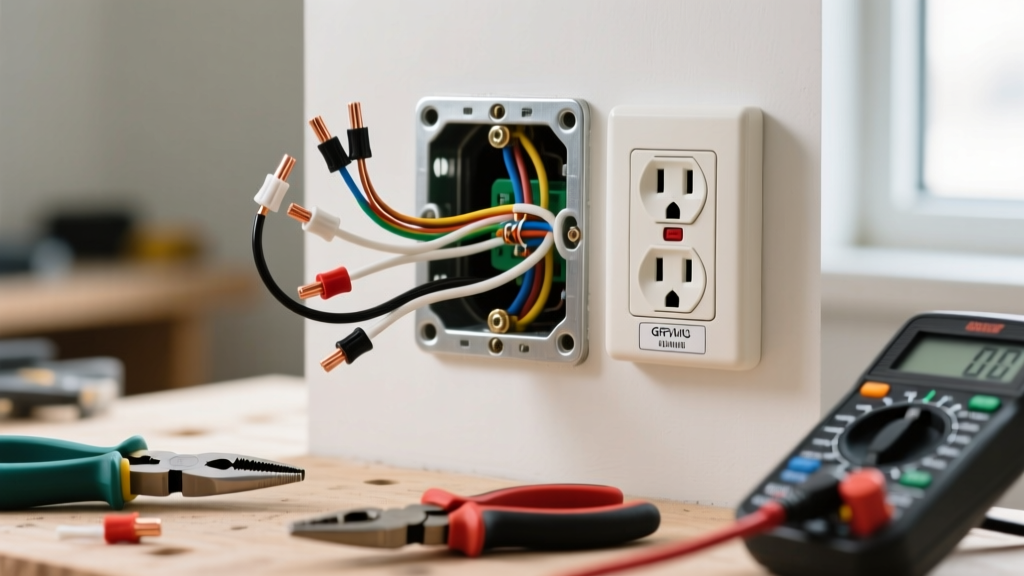
Safety is paramount. Shut off the 50-amp double-pole breaker at the main service panel and verify the absence of voltage using your NCVT and DMM. Once confirmed dead, remove the NEMA 14-50R receptacle from the junction box.
1. Wire Gauge and Type Verification
Inspect the feeder cables entering the box. For a standard 50-amp stove circuit, the National Electrical Code (NEC) requires a minimum of 6 AWG copper or 4 AWG aluminum. If you find 8 AWG copper wire on a 50-amp breaker, this is a severe code violation and a fire hazard; the breaker must be swapped to 40A, or the wire must be upgraded.
2. Insulation and Stripping Integrity
Check the wire insulation for scoring or nicks caused by overzealous stripping. The bare copper should not extend more than 1/16th of an inch beyond the terminal lug. Exposed bare wire outside the terminal increases the risk of accidental shorting against the metal junction box or adjacent terminals.
3. NEC 110.14(D) Torque Verification
Code Alert: Since the 2017 NEC update, and strictly enforced in 2026, NEC Article 110.14(D) mandates that all electrical terminations must be tightened to the manufacturer's specified torque using a calibrated tool. Guessing 'finger tight' is no longer compliant.
For a standard Leviton 279-S00 50-amp receptacle, the terminal screws require 45 in-lbs (5.08 Nm) of torque. Use your calibrated screwdriver to verify that the X (Hot 1), Y (Hot 2), W (Neutral), and G (Ground) terminals are secured to this exact specification. Loose connections cause arcing; overtightened connections strip threads and crush wire strands, reducing the effective cross-sectional area.
Phase 2: Live Voltage and Polarity Testing
Reinstall the receptacle, ensure the cover plate is secured, and re-energize the 50-amp breaker. Set your DMM to AC Voltage (V~). Refer to the Fluke Electrical Safety Guide for proper probe handling and PPE requirements when testing live 240V circuits.
Expected Voltage Matrix for NEMA 14-50R
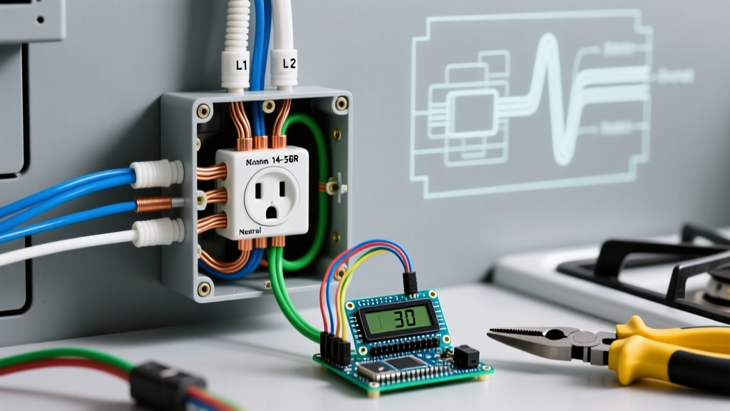
Insert your probes into the appropriate slots. The top slot is Ground (G), the bottom center is Neutral (W), and the left/right angled slots are Hot (X and Y).
| Test Points | Expected Reading | Indicates | Common Fault if Incorrect |
|---|---|---|---|
| Hot 1 (X) to Hot 2 (Y) | 240V (±5%) | Proper 240V feed | Tripped breaker, lost phase, or 120V miswire |
| Hot 1 (X) to Neutral (W) | 120V (±5%) | Leg 1 to Neutral | Open neutral or reversed polarity |
| Hot 2 (Y) to Neutral (W) | 120V (±5%) | Leg 2 to Neutral | Open neutral or reversed polarity |
| Hot 1 (X) to Ground (G) | 120V (±5%) | Leg 1 to Ground | Open ground or bootleg ground |
| Hot 2 (Y) to Ground (G) | 120V (±5%) | Leg 2 to Ground | Open ground or bootleg ground |
| Neutral (W) to Ground (G) | < 1.0V (Ideally 0V) | Separate Neutral/Ground | Neutral-Ground bond at receptacle (Code Violation) |
Phase 3: Thermal Imaging and Load Testing
Voltage testing only proves the circuit is alive; it does not prove the connections can handle a sustained 12,000-watt load without thermal failure. Resistive heating occurs at loose or oxidized termination points.
- Turn on the electric stove. Set all four surface burners to 'HIGH' and activate the oven bake element to 450°F.
- Allow the stove to run under this maximum load for exactly 15 minutes.
- Using your infrared thermometer, scan the receptacle faceplate and the junction box cover. Then, scan the adjacent wall surface to establish an ambient baseline temperature.
- The Delta T Rule: If the receptacle faceplate or the area immediately surrounding the terminal screws is more than 15°C (27°F) hotter than the ambient wall temperature, you have a high-resistance connection. De-energize immediately, re-strip the wires, apply antioxidant compound (if aluminum), and re-torque to 45 in-lbs.
Common Failure Modes and Edge Cases
The 3-Prong vs. 4-Prong Dilemma (NEC 250.140)
Older homes often feature 3-prong NEMA 10-50R outlets, where the neutral and ground were bonded at the appliance. For any new installation or modified circuit, NEC 250.140 strictly prohibits this. You must install a 4-prong NEMA 14-50R and ensure the stove's internal bonding strap (which connects neutral to the chassis ground) is removed. Failing to remove this strap on a 4-wire system creates a parallel neutral path, causing current to flow on the ground wire and potentially energizing the stove chassis.
Aluminum Wire Creep and Oxidation
If your home was wired in the 1970s or uses modern 4 AWG aluminum feeders to save costs, aluminum is susceptible to 'cold creep' (expanding and contracting under heat, loosening the terminal grip over time). Furthermore, bare aluminum oxidizes rapidly. You must apply a UL-listed antioxidant paste like Noalox or Penetrox to the stripped aluminum conductors before inserting them into the receptacle terminals to prevent micro-arcing.
Undersized Breakers and Nuisance Tripping
Some DIYers attempt to wire a 50-amp stove receptacle to a 40-amp breaker to 'be safe.' This violates NEC 210.19(A)(1), which requires branch circuits to be rated not less than the noncontinuous load plus 125% of the continuous load. If the stove's nameplate specifies a minimum 50A circuit, a 40A breaker will nuisance-trip during heavy holiday cooking sessions and may degrade thermally over time.
Frequently Asked Questions (FAQ)
Can I use 6/3 NM-B (Romex) for a 50-amp stove outlet?
Yes, in most jurisdictions, 6/3 NM-B with ground is permitted for a 50-amp indoor residential stove circuit, as its ampacity is rated at 55 amps. However, if the run exceeds 75 feet, you must calculate voltage drop and may need to upsize to 4 AWG copper. Always check with your local Authority Having Jurisdiction (AHJ), as some municipalities mandate THHN/THWN-2 wires in conduit for all 50-amp appliance circuits.
Why is my stove humming when connected to the outlet?
A low-frequency hum usually originates from the stove's internal transformers or induction elements, not the outlet. However, if the hum is accompanied by a buzzing sound at the receptacle faceplate, this indicates severe arcing due to loose terminal screws. Shut off the breaker immediately and perform the torque verification outlined in Phase 1.
Is GFCI protection required for stove outlets?
Under the 2023 and 2026 NEC updates, GFCI protection is generally not required for dedicated 240V electric range receptacles unless the outlet is located within 6 feet of a sink or an unfinished basement area, depending on local amendments. AFCI protection, however, is increasingly mandated by local codes for kitchen branch circuits. Consult your local electrical inspector for precise regional adoptions.