
Mastering the Electrical Outlet Receptacle Installation
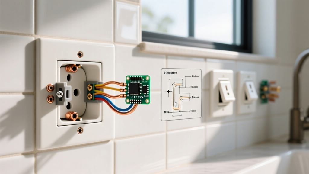
Installing a standard 15-amp electrical outlet receptacle is a foundational skill in residential and commercial wiring. While the process may seem straightforward, improper terminations, ignored box-fill calculations, and reliance on outdated push-in connectors are leading causes of electrical fires and voltage drops. As of 2026, industry best practices heavily favor commercial-specification grade receptacles over builder-grade alternatives due to their superior internal yoke stability and terminal grip. This guide provides a rigorous, step-by-step methodology for wiring a 125V, 15-amp duplex electrical outlet receptacle, adhering strictly to modern safety protocols and the latest National Electrical Code (NEC) standards.
Essential Tools and Materials Matrix
Using the correct, calibrated tools is non-negotiable for achieving secure terminations and preventing conductor damage. Below is the recommended loadout for a standard 15A receptacle installation in 2026.
| Item Category | Specific Brand / Model | Purpose & Specification | Est. 2026 Cost |
|---|---|---|---|
| Receptacle | Leviton 5262-CA (Commercial Spec) | 15A, 125V, Tamper-Resistant, side/backscrew wired | $3.80 - $4.50 |
| Wire Stripper | Klein Tools 11055 | Precision stripping for 10-20 AWG solid/stranded wire | $28.00 |
| Torque Screwdriver | Klein Tools 69010 | Calibrated to 14 in-lbs for terminal screws | $145.00 |
| Wire Connectors | Ideal 33-080 (Blue) | Secure pigtailing for 14 and 12 AWG copper conductors | $0.12 / ea |
| Tester | Klein Tools RT250 | GFCI and standard receptacle wiring verification | $34.00 |
Phase 1: Pre-Installation Safety and Box Inspection
Before exposing any conductors, you must eliminate the risk of arc flash or shock. Always adhere to OSHA Lockout/Tagout standards by turning off the corresponding circuit breaker and securing the panel with a physical lockout device. Verify the absence of voltage using a non-contact voltage tester (NCVT) and confirm it on a known live source before and after testing the target box.
Verifying Box Fill and Conductor Count
Per NEC Article 314, you must ensure the electrical box has adequate volume for the conductors, clamps, and the receptacle yoke itself. A standard single-gang metal or plastic box (typically 18 to 22 cubic inches) can comfortably house one 15-amp receptacle, one incoming 14/2 or 12/2 NM cable, and one outgoing cable. If you are adding pigtails for grounding or neutral continuity, remember that all equipment grounding conductors combined count as a single conductor fill allowance, while each current-carrying conductor (hot and neutral) counts individually.
Phase 2: Step-by-Step Wiring Procedure
Step 1: Precision Conductor Preparation
Strip the outer NM cable jacket back to exactly 1/4 inch inside the box clamp to prevent exposed bare wire from shorting against a metal box edge. Next, strip the individual 14 AWG or 12 AWG copper conductors. Use the strip gauge molded into the back of the Leviton 5262 receptacle body—typically 3/4 inch for side wiring. Never nick the copper conductor during stripping; a nick creates a localized stress point that can lead to thermal failure under sustained 15-amp loads.
Step 2: Forming the Terminal J-Hook
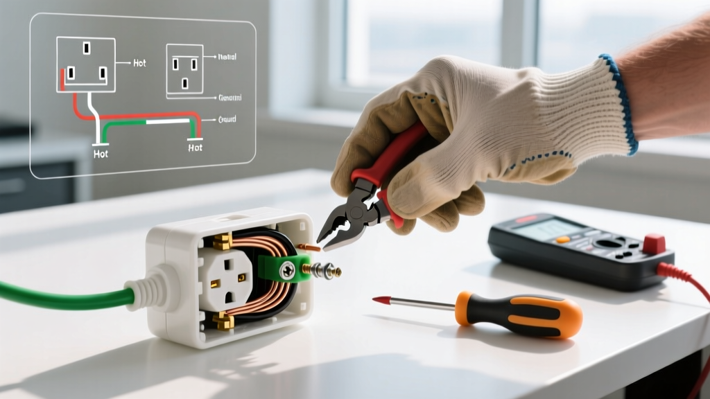
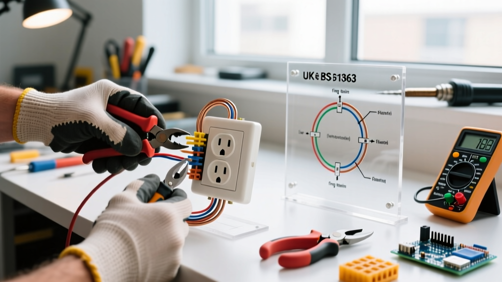
Using needle-nose pliers, bend the stripped end of the conductor into a tight 'J' hook. The loop must be perfectly round and sized so that it sits entirely beneath the head of the terminal screw without overlapping the wire insulation. If bare wire extends past the screw head, it creates a shock hazard and a potential short-circuit path to adjacent grounded surfaces.
Step 3: Side-Wiring to Brass and Silver Terminals
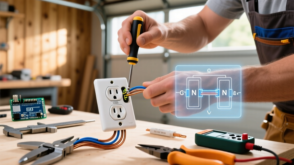
Connect the black (hot) wire to the brass-colored screw and the white (neutral) wire to the silver-colored screw. Always loop the wire clockwise around the screw. As you tighten the screw, the clockwise rotation will pull the J-hook tighter beneath the head. If looped counter-clockwise, the tightening action will push the wire out from under the screw, resulting in a high-resistance connection.
Expert Insight: While residential inspectors rarely mandate torque verification for standard 15A receptacles, the industry-accepted torque for 14-12 AWG copper on brass terminal screws is 14 in-lbs. Using a calibrated torque screwdriver prevents 'cold flow' deformation of the copper and ensures long-term thermal stability.
Step 4: Equipment Grounding and Pigtailing
Attach the bare copper or green insulated ground wire to the green grounding screw. If you are installing in a metal electrical box, NEC 250.148 requires you to bond the receptacle's ground to the box itself. Do not rely solely on the mounting screws for this bond. Instead, use a green grounding pigtail with a grounding clip attached to the box edge, or use a self-grounding receptacle equipped with a copper bonding strap that contacts the mounting yoke.
Phase 3: Critical Failure Modes to Avoid
Understanding how receptacles fail in the field separates amateur work from professional-grade installations. Avoid these common pitfalls:
- The 'Backstab' Push-In Trap: Never use the push-in (backstab) holes on the back of a builder-grade receptacle. These rely on a small internal spring-wedge to grip the wire. Over years of thermal expansion and contraction (heating up under load, cooling down at rest), the spring tension degrades, leading to arcing, melted plastic, and open circuits. Always use side-wiring or commercial-grade screw-clamp back-wiring.
- Daisy-Chaining Neutrals on MWBCs: If your circuit is a Multi-Wire Branch Circuit (sharing a neutral between two hot phases), you must pigtail the neutral wire. Breaking the neutral path by feeding it through the receptacle's silver terminal to the next outlet will result in 240V being forced across 120V appliances downstream if the receptacle is ever removed for service.
- Over-tightening Terminal Screws: Applying excessive force can strip the brass threads or snap the screw head, compromising the clamp pressure and creating a high-impedance fault point.
Phase 4: NEC Code Compliance and Tamper Resistance
As outlined by the National Fire Protection Association (NFPA 70), all 15-amp and 20-amp, 125V and 250V non-locking electrical outlet receptacles installed in dwelling units must be Tamper-Resistant (TR). TR receptacles feature internal shutters that only open when equal, simultaneous pressure is applied to both slots (as with a standard plug). This prevents children from inserting foreign objects like hairpins or keys into the hot slot. Ensure the 'TR' stamp is clearly visible on the face of the receptacle yoke before installation.
Phase 5: Folding, Mounting, and Final Testing
Carefully fold the conductors into the back of the box using an accordion or 'S' fold. Pushing the wires straight back can pinch them against the sharp metal edges of the box clamps, compromising the insulation. Mount the receptacle using the top and bottom 6-32 machine screws, ensuring the yoke sits flush against the drywall or plaster ring without overtightening, which can warp the plastic face and cause plug insertion issues.
The Verification Protocol
Restore power at the breaker panel. Insert a Klein RT250 or equivalent receptacle tester. The indicator lights must confirm 'Correct Wiring' (typically two yellow/amber lights, depending on the model). Furthermore, press the GFCI test button on the tester if the circuit is GFCI-protected upstream; the upstream breaker or receptacle should trip immediately. Finally, test the physical grip of the TR shutters by inserting a standard plug—it should slide in smoothly without requiring excessive force, indicating the internal mechanism is properly aligned and unbound.