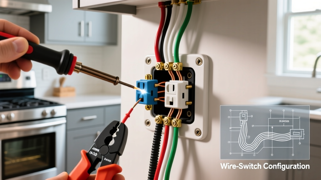

The Global Terminology Divide: 2-Way vs. 3-Way Switches
Before grabbing your wire strippers, we must address a critical terminology gap that causes countless DIY electrical failures. If you are searching for a wiring diagram for 2 way light switch circuits, your physical location dictates the components you need. In the UK, Australia, New Zealand, and regions following IEC standards (BS 7671), a 2-way switch allows you to control a single light fixture from two separate locations (e.g., the top and bottom of a staircase). However, in North America, the National Electrical Code (NEC) refers to this exact same functionality as a 3-way switch circuit. Conversely, what North Americans call a 'single-pole' switch (one location control) is often referred to as a '1-way' switch in the UK.
This guide uses the international '2-way' terminology to match your search intent, but provides exact North American '3-way' equivalents in parentheses to ensure global safety, code compliance, and practical application. Always verify your local electrical codes before beginning any mains voltage work.
Core Components and Cable Requirements
A standard 2-way (or US 3-way) circuit requires specialized switches and an additional 'traveler' wire compared to a standard single-location switch. You cannot use standard single-pole/1-way switches for this setup; the internal brass terminal architecture is fundamentally different.
| Feature | UK / AUS / IEC Standard (2-Way) | US / Canada NEC Standard (3-Way) |
|---|---|---|
| Switch Terminals | COM (Common), L1, L2 | Common (Dark Screw), Traveler 1, Traveler 2 (Brass Screws) |
| Interconnect Cable | 1.0mm² or 1.5mm² 3-Core + Earth | 14/3 or 12/3 NM-B (Romex) with Ground |
| Traveler Wire Colors | Brown, Black, Grey (or Red/Blue/Yellow in older installs) | Red, Black, and White (White must be re-identified with black tape) |
| Breaker Size (Typical) | 6A or 10A MCB (Type B or C) | 15A (14 AWG) or 20A (12 AWG) AFCI Breaker |
Method 1: Wiring Diagram for 2 Way Light Switch (Loop at the Switch)
The 'Loop at the Switch' method is the modern standard for IEC regions and is increasingly common in North American retrofits. In this configuration, the permanent live feed enters the first switch box, and the travelers carry the switched live to the second switch, which then feeds the light fixture. The neutral wire completely bypasses the switches and runs directly to the ceiling rose or fixture junction box.
Step-by-Step Wiring Procedure
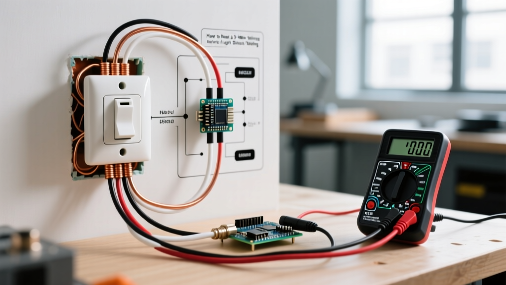
- Isolate and Verify: Turn off the mains breaker. Use a non-contact voltage tester (e.g., Fluke 1AC-II VoltAlert) and a multimeter set to AC Voltage to confirm zero potential at the working terminals.
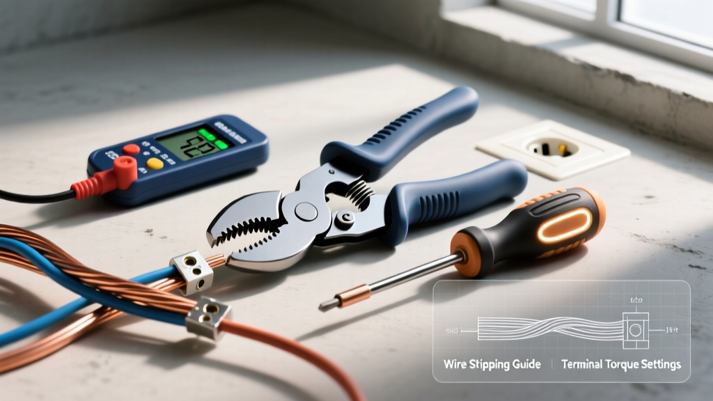
- Prepare the Interconnect Cable: Run your 3-core cable between Switch Box 1 and Switch Box 2. Strip exactly 12mm (1/2 inch) of insulation from the traveler wires using precision strippers like the Klein Tools 11063W to prevent nicking the copper conductor, which creates a hot-spot failure point.
- Wire Switch 1 (Power Entry): Connect the incoming permanent Live (Brown/Black) to the COM (Common) terminal on Switch 1. Connect the two traveler wires to the L1 and L2 terminals. (Note: Polarity between L1 and L2 does not matter; it only dictates whether the switches operate in the same or opposite physical directions).
- Wire Switch 2 (Light Feed): Connect the corresponding traveler wires from the 3-core cable to the L1 and L2 terminals on Switch 2. Connect a single core wire (the switched live) from the COM terminal on Switch 2 directly to the Live terminal on your light fixture.
- Complete the Neutral and Earth: Connect all Neutral wires (Blue/White) together using WAGO 221 lever nuts or appropriate wire nuts. Connect all bare Earth/Ground wires to the metal backboxes and the earth terminal on the light fixture. If using metal switch plates, pigtail the earth to the plate's grounding screw.
Method 2: Alternative Diagram (Loop at the Ceiling Rose)
In older installations, particularly in the UK and Australia, the 'Loop at the Ceiling' method was standard. Here, the permanent live and neutral both enter the ceiling rose first. A 3-core cable drops down to Switch 1, and another 3-core drops to Switch 2. This method uses more cable and is generally discouraged in new 2026 construction due to the complexity of troubleshooting junction boxes hidden in ceiling cavities, but you will inevitably encounter it in heritage homes.
Expert Troubleshooting Tip: If you open a ceiling rose and find three separate cables with 4 wires each, you are likely looking at a looped ceiling 2-way circuit. Map the permanent live, the switched live return, and the traveler interconnects using a continuity tester before disconnecting a single wire.
Upgrading 2-Way Circuits to Smart Switches (2026 Standards)
The physical traveler wires in a 2-way circuit are a major headache when upgrading to smart home ecosystems. Most standard smart switches (like the basic TP-Link Kasa or older Philips Hue wall modules) require a neutral wire at the switch box and do not support physical traveler wiring. If you wire travelers directly into a standard smart switch, you will cause a dead short and destroy the internal triac.
The Digital Bypass Solution
To modernize a 2-way staircase setup without pulling new cables, use a smart relay installed at the light fixture (ceiling rose), and convert the physical wall switches into 'dumb' momentary inputs or digital toggles.
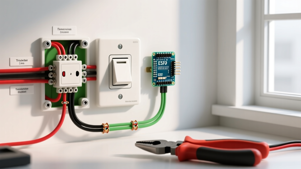
- Shelly Plus 1PM (Approx. $22 USD): Install this compact relay at the ceiling fixture. Connect the permanent live and neutral to the relay. Cap off the physical traveler wires in the wall boxes safely. Wire standard momentary push-buttons to the Shelly's SW input. The Shelly handles the logic, and you can control the light via Matter over Thread, Wi-Fi, or the physical buttons.
- Lutron Caseta Claro (Approx. $65 USD): For the North American market, install the Caseta smart switch at the location where power enters (Line/Load/Neutral). At the second location, cap the travelers and install the Pico Remote wallplate bracket. This eliminates the need for a neutral at the second location entirely and complies fully with NEC wireless control standards.
Troubleshooting Common 2-Way Wiring Faults
Even with a perfect wiring diagram for 2 way light switch setups, DIYers frequently encounter specific failure modes. Use this diagnostic matrix to identify your issue without guessing.
| Symptom | Probable Cause | Diagnostic Action |
|---|---|---|
| Light only works if Switch A is UP, regardless of Switch B's position. | Broken traveler wire or loose connection on L1/L2 between the two switches. | Set multimeter to continuity. Test between L1 on Switch 1 and L1 on Switch 2 with power OFF. Repeat for L2. |
| Breaker trips instantly when toggling either switch. | Switched Live (from COM on Switch 2) is shorted to Earth, or Neutral is bonded to Earth at the fixture. | Disconnect the load wire at Switch 2 COM. Reset breaker. If it holds, the fault is in the ceiling fixture wiring. |
| LED bulbs flicker or glow faintly when switched OFF. | Induced voltage on long traveler runs acting as a capacitor, or lack of a neutral at the fixture. | Install a 0.1µF X2 suppression capacitor (or a Lutron LUT-MLC) in parallel with the LED fixture at the ceiling. |
Safety, Code Compliance, and Final Verification
Electrical wiring is unforgiving. A loose terminal screw torqued to less than the manufacturer's specification can increase contact resistance, leading to thermal runaway and electrical fires. According to the NFPA National Electrical Code (NEC), all 15A and 20A residential lighting circuits in living areas, hallways, and staircases must now be protected by Arc-Fault Circuit Interrupters (AFCIs). This means your 2-way circuit must originate from an AFCI breaker in the main panel, not a standard thermal-magnetic breaker.
For international readers, the IET Wiring Regulations (BS 7671) mandate strict adherence to cable color coding and routing depths to prevent accidental nail strikes in stud walls. Furthermore, the Occupational Safety and Health Administration (OSHA) emphasizes that lockout/tagout (LOTO) procedures are not just for industrial sites; physically locking your consumer unit or breaker panel with a padlock while working on a 2-way staircase circuit prevents fatal accidental re-energization by other household members.
Before energizing the circuit for the first time, perform a dead-test. Use a low-resistance ohmmeter to verify continuity between the main earth terminal and the metal switch plates. Ensure the resistance is below 0.5 ohms. Once verified, restore power, test the mechanical toggling from both locations, and use a thermal camera or infrared thermometer to check the switch faceplates after 30 minutes of continuous high-wattage load to ensure no abnormal heat generation is occurring at the terminal connections.