
The Definitive Guide to Wiring an Electric Outlet in 2026
Wiring an electric outlet is one of the most common residential electrical tasks, yet it remains a frequent source of household fires when executed improperly. According to the Electrical Safety Foundation International (ESFI), electrical receptacles are involved in thousands of residential fires annually, often stemming from loose connections, overloaded circuits, or incorrect daisy-chaining.
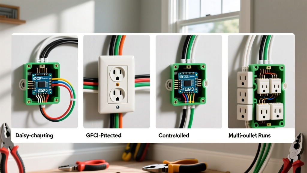
As of the 2026 National Electrical Code (NEC) adoption cycle, the requirements for tamper-resistant (TR) receptacles, arc-fault (AFCI), and ground-fault (GFCI) protection have expanded. Whether you are replacing a damaged receptacle or extending a circuit, understanding the exact topology of your wiring scenario is critical. This guide breaks down the four most common electric outlet wiring scenarios, complete with exact torque specifications, termination best practices, and NEC compliance rules.
Essential Tools for the Job
Before opening any junction box, ensure you have the right diagnostic and termination tools. Relying on outdated gear compromises safety.
- Voltage Tester: Klein Tools NCVT-3 (Dual-range non-contact tester, ~$35). Always test before and after turning off the breaker.
- Torque Screwdriver: Wiha 32050 Insulated Torque Screwdriver set to 14 in-lbs. (More on this below).
- Wire Connectors: Wago 221-413 Lever Nuts (~$0.45 each). Superior to twist-on wire nuts for maintaining clamp pressure over time.
- Wire Strippers: Klein Tools 11063W (Katapult) for clean 14 AWG and 12 AWG strips without nicking the copper.
Scenario 1: End-of-Run (Single Cable Entry)
The simplest scenario is an electric outlet located at the very end of a branch circuit. Only one Romex (NM-B) cable enters the junction box.
Step-by-Step Termination
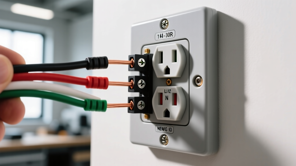
- Prepare the Wires: Strip 3/4 inch of insulation from the black (hot), white (neutral), and bare copper (ground) wires.
- Ground First: Always terminate the ground wire first. Attach the bare copper to the green grounding screw on the receptacle.
- Neutral Connection: Connect the white wire to the silver terminal screw.
- Hot Connection: Connect the black wire to the brass terminal screw.
Pro Tip: When wrapping the wire around the terminal screw, always loop it in a clockwise direction. This ensures that as you tighten the screw (righty-tighty), the loop pulls tighter around the shaft rather than splaying outward.
Scenario 2: Middle-of-Run (Daisy-Chaining)
When the electric outlet sits in the middle of a circuit, two cables enter the box: one bringing power from the panel (line) and one carrying power to the next downstream device (load).
The 'Pigtail' Method vs. Continuous Loop
Many DIYers simply connect both black wires to the single brass screw using the side-wire clamp, or daisy-chain them through the push-in holes. Do not do this. If the receptacle fails or is removed for testing, the entire downstream circuit loses power. Furthermore, NEC 300.13(B) requires that the continuity of the grounded (neutral) conductor must not depend on device connections.
How to Pigtail Correctly
- Take the two black (hot) wires from the cables and add a 6-inch piece of 14 AWG or 12 AWG black wire (matching the circuit gauge).
- Secure all three wires together using a Wago 221-413 lever nut.
- Connect the free end of the 6-inch pigtail to the brass screw on the receptacle.
- Repeat this exact process for the white (neutral) wires, connecting them to the silver screw via a white pigtail.
- Combine all bare ground wires with a green grounding pigtail using a wire nut or lever connector, and attach to the green screw.
Scenario 3: GFCI Protection (Kitchens, Bathrooms, and Outdoors)
NEC Article 210.8 mandates Ground-Fault Circuit Interrupter (GFCI) protection for all 125-volt, single-phase, 15- and 20-ampere receptacles in damp or wet locations. A GFCI receptacle monitors the current balance between the hot and neutral wires, tripping in milliseconds if a variance as small as 4 to 6 milliamps is detected.
Line vs. Load: The Most Common Mistake
GFCI receptacles feature two distinct sets of terminals: LINE and LOAD.
- LINE Terminals: These connect to the incoming power source from the breaker panel. They are usually marked with a piece of yellow tape over the LOAD terminals to prevent confusion.
- LOAD Terminals: These feed power to downstream standard receptacles, extending GFCI protection to them.
The Edge Case: If you accidentally wire the incoming power to the LOAD terminals, the GFCI will not reset, or worse, it will provide power but fail to offer ground-fault protection. Always use your non-contact voltage tester to identify the live incoming cable before making connections.
Scenario 4: Split-Wired Receptacles (Switched Half)
In living rooms without overhead lighting, or on kitchen countertops, you may encounter a split-wired electric outlet. Here, the top half is controlled by a wall switch (for a lamp), while the bottom half remains constantly hot for appliances.
Breaking the Brass Fin
A standard duplex receptacle has a small metal tab (fin) connecting the two brass hot screws. To create a split-wired scenario:
- Locate the brass fin on the hot side of the receptacle.
- Use a pair of needle-nose pliers to bend the tab back and forth until it snaps off completely. (Do not break the silver fin on the neutral side).
- Connect the always-hot black wire from the panel to one brass screw.
- Connect the switched-hot wire (often red or black with tape) returning from the wall switch to the other brass screw.
- Wire the neutral and ground as standard.
15A vs. 20A Electric Outlet Specifications
Selecting the correct receptacle rating for your branch circuit is a fundamental NEC requirement. Installing a 20A receptacle on a 15A circuit is a violation, while installing a 15A receptacle on a 20A circuit is only permitted if there are multiple receptacles on the circuit (NEC Table 210.21(B)(3)).
| Feature | 15A Receptacle (NEMA 5-15R) | 20A Receptacle (NEMA 5-20R) |
|---|---|---|
| Wire Gauge Required | 14 AWG or 12 AWG | 12 AWG or 10 AWG |
| Breaker Size | 15 Amp | 20 Amp |
| Slot Configuration | Two parallel vertical slots | One vertical, one T-shaped (horizontal) |
| Typical Use Case | Bedrooms, Living Rooms, Hallways | Kitchens, Bathrooms, Garage Workshops |
| Avg. Retail Cost (2026) | $2.50 - $4.00 | $4.50 - $7.50 |
Termination Methods: Why 'Backstabbing' is a Fire Hazard
Modern electric outlets typically offer three ways to terminate a wire. Understanding the mechanical differences is vital for long-term reliability.
1. Push-In (Backstab) Terminals
You simply strip the wire and push it into a small hole in the back of the device. A tiny internal brass spring clip bites into the copper.
Verdict: AVOID. The contact surface area is minuscule. Under high continuous loads (like a 1500W space heater drawing 12.5A), the spring clip can overheat, lose tension, and cause arcing. Many professional electricians refuse to use backstab connections entirely.
2. Side-Wire (Screw Terminal)
The traditional method of looping the stripped wire around the terminal screw.
Verdict: GOOD. Reliable when done correctly. However, 12 AWG wire is very stiff and can be difficult to loop tightly without breaking the copper strands.
3. Back-Wire (Internal Clamp)
Found on commercial-grade and high-end residential receptacles (like the Leviton T5262-W). You insert the straight stripped wire into a hole on the back, and tightening the side screw pulls a heavy-duty metal plate down onto the wire, clamping it securely.
Verdict: BEST. Maximizes contact surface area, requires less physical force to terminate 12 AWG wire, and completely eliminates the risk of loose loops.
The Critical Role of Torque Specifications
One of the most overlooked aspects of wiring an electric outlet is terminal screw torque. The National Fire Protection Association (NFPA) and the NEC explicitly require that connections be tightened to the manufacturer's specified torque values.
Most UL-listed 15A and 20A receptacles specify a torque value between 12 and 16 inch-pounds (in-lbs). Hand-tightening is no longer considered an acceptable industry standard.
- Under-torquing: Leads to micro-movements, oxidation, increased resistance, and ultimately thermal failure (melting the receptacle face).
- Over-torquing: Strips the brass threads or snaps the screw head off inside the yoke.
Invest in an insulated torque screwdriver calibrated to 14 in-lbs. It takes three extra seconds per terminal and virtually eliminates connection-based failures.
Final Safety and Inspection Checklist
Before buttoning up the junction box and restoring power, run through this final checklist to ensure your installation meets 2026 safety standards:
- Tamper-Resistant (TR) Mark: Ensure the receptacle has the 'TR' stamp. NEC 406.12 requires TR receptacles in almost all dwelling unit areas to prevent children from inserting foreign objects.
- Box Fill Capacity: Verify the junction box is not overfilled. A standard single-gang plastic box (18 cubic inches) can comfortably hold one receptacle, two 14/2 cables, and wire nuts. If you are pigtailing heavily, you may need a 22-cubic-inch deep box.
- Plaster Ears: If the drywall cutout is slightly too large, ensure the receptacle's plaster ears (the small metal tabs on the top and bottom of the yoke) are resting firmly against the drywall to prevent the device from pushing into the wall when plugging in a cord.
- Re-test: Turn the breaker back on and use a 3-prong receptacle tester (like the Sperry ET6402) to verify correct wiring and GFCI trip functionality.
By adhering to these specific scenarios, utilizing modern termination hardware, and respecting torque specifications, you ensure your electric outlet installations are safe, durable, and fully compliant with modern electrical codes.