
The Modern Electric Stove Power Outlet: Beyond the Basics
As kitchen electrification accelerates in 2026, the transition from gas to high-wattage induction and dual-fuel ranges has made the electric stove power outlet one of the most critical circuits in the modern home. Unlike standard 15-amp or 20-amp receptacles, a range circuit demands a dedicated 50-amp, 240-volt supply capable of handling continuous loads upwards of 12,000 watts. Whether you are upgrading an older kitchen or wiring a new construction project, understanding the exact wiring diagram, National Electrical Code (NEC) requirements, and termination specifications is non-negotiable for safety and performance.
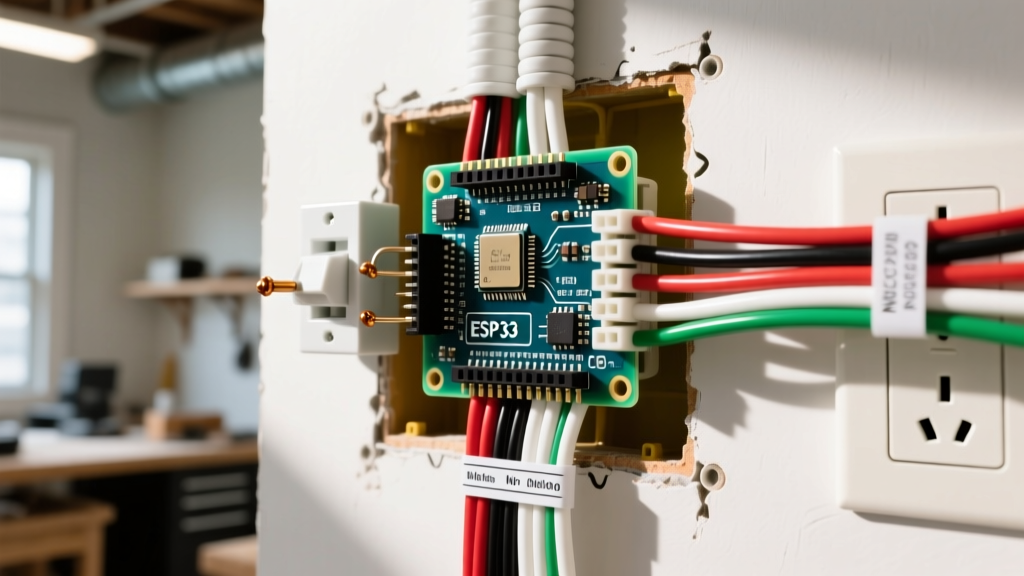
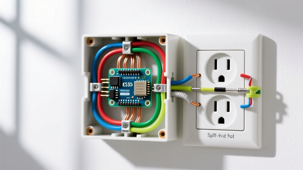
This comprehensive wiring diagram reference focuses on the industry-standard NEMA 14-50R receptacle. We will break down the physical wiring topology, contrast legacy 3-prong setups with modern 4-prong mandates, and provide exact torque specifications to prevent thermal failures at the terminal block.
Decoding the NEC: Article 250 and Range Receptacles
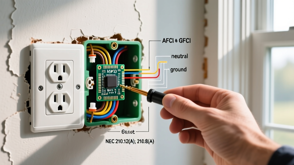
The National Fire Protection Association (NFPA) outlines strict guidelines for appliance grounding in NEC Article 250. For decades, electric ranges were permitted to use the neutral conductor as a grounding path (the legacy 3-prong setup). However, modern NEC editions strictly prohibit this for new installations. All new electric stove power outlet installations must feature an isolated, dedicated equipment grounding conductor.
Safety Warning: Before opening your main service panel or touching any branch circuit wiring, shut off the main breaker and verify the absence of voltage using a CAT III or CAT IV rated non-contact voltage tester and a digital multimeter. Never assume a circuit is dead based solely on the breaker position.
According to NEC Article 210.19 and Article 422, the branch circuit rating must be at least the minimum branch-circuit rating specified by the appliance manufacturer. While some older electric freestanding ranges draw less than 40 amps, nearly all modern induction ranges and commercial-style dual-fuel models require a full 50-amp circuit. Furthermore, the receptacle itself must comply with ANSI/NEMA WD-6 dimensional specifications to ensure proper pin alignment and grounding integrity.
NEMA 10-50 vs. NEMA 14-50: The 3-Prong vs. 4-Prong Divide
One of the most common points of confusion for DIYers and junior electricians is the difference between the legacy NEMA 10-50 and the modern NEMA 14-50. Below is a structural comparison to clarify the wiring topology.
| Feature | NEMA 10-50 (3-Prong) | NEMA 14-50 (4-Prong) |
|---|---|---|
| Wire Count | 3 (Hot, Hot, Neutral/Ground) | 4 (Hot, Hot, Neutral, Ground) |
| Grounding Path | Neutral conductor (Bonded at appliance) | Dedicated Equipment Grounding Conductor (EGC) |
| NEC Status (New Installs) | Prohibited / Obsolete | Mandatory Standard |
| Appliance Cord | 3-wire cord (Neutral bonded to frame) | 4-wire cord (Neutral isolated from frame) |
| Safety Risk | High (Shock hazard if neutral breaks) | Low (Independent fault clearing path) |
Note: If you are replacing an old range in a home that still has a 3-prong NEMA 10-50 receptacle, the NEC allows you to keep the 3-prong outlet and use a 3-prong cord, provided you bond the neutral to the frame at the appliance. However, best practice in 2026 is to upgrade the circuit to a 4-wire NEMA 14-50R to eliminate the shock hazard entirely.
Wiring Diagram Reference: 50-Amp NEMA 14-50R Installation
The following step-by-step guide details the installation of a surface-mounted or flush-mounted NEMA 14-50R receptacle. We recommend premium commercial-grade receptacles like the Leviton 279-S00 or the Hubbell 9450A, which feature heavy-duty brass contacts and robust thermoplastic housings designed to withstand high thermal loads.
Required Materials and Tooling
- Receptacle: Leviton 279-S00 (50A, 125/250V, NEMA 14-50R)
- Breaker: 50-Amp, 240-Volt Double-Pole (e.g., Square D HOM250CP or Siemens Q250, matched to your panel brand)
- Conductors: 6 AWG Copper THHN/THWN-2 (Black, Red, White, Green) OR 4 AWG Aluminum XHHW
- Electrical Box: 2-Gang deep metallic or non-metallic box (minimum 42 cubic inches for 6 AWG wire fill)
- Tools: Wire strippers, torque screwdriver (calibrated to inch-pounds), digital multimeter, fish tape
Step 1: Panel Preparation and Breaker Installation
Route your 6 AWG 4-conductor cable from the main service panel to the kitchen location. At the panel, connect the bare copper (or green) ground wire to the equipment grounding busbar. Connect the white neutral wire to the isolated neutral busbar. Seat the 50-amp double-pole breaker into the panel bus stabs. Terminate the black and red hot conductors onto the breaker's lug screws. Crucial: If using aluminum wire, you must apply a UL-listed anti-oxidant compound (like Noalox) to the wire strands before termination to prevent galvanic corrosion and subsequent arcing.
Step 2: Routing and Box Mounting
For surface mounting, use a 2-gang surface box. For flush mounting, ensure the drywall cutout is precise and the box is securely fastened to a structural stud. The standard height for an electric stove power outlet is typically 10 to 12 inches above the finished floor, positioned centrally behind the range cavity. Ensure the cable enters the box with at least 1/4 inch of sheathing extending inside the knockout, secured by an appropriate cable clamp.
Step 3: Termination and Precision Torquing
Strip exactly 3/4 inch of insulation from the four conductors. The NEMA 14-50R terminal layout is standardized:
- X (Left Hot): Terminate the Black wire.
- Y (Right Hot): Terminate the Red wire.
- W (Neutral): Terminate the White wire to the silver-colored screw.
- G (Ground): Terminate the Green/Bare wire to the green grounding screw.
The most overlooked step in high-amperage wiring is mechanical torque. According to manufacturer specifications and NEC 110.14(D), terminals must be tightened to the manufacturer's prescribed torque. For the Leviton 279-S00, the target torque is 45 in-lbs. Using a calibrated torque screwdriver (such as the Klein Tools 69045) ensures the wire is compressed sufficiently to prevent micro-arcing and thermal expansion loosening, which are the primary causes of melted receptacles and electrical fires.
Troubleshooting Common Range Outlet Failures
Even with a perfect wiring diagram reference, issues can arise. According to the Electrical Safety Foundation International (ESFI), kitchen circuits account for a significant percentage of residential electrical hazards. Here is how to troubleshoot common failures:
- Symptom: Range display lights up, but burners do not heat.
Diagnosis: You likely have a lost leg (one of the 120V hot phases is dead). Use a multimeter to test L1 to L2 (should read 240V), L1 to Neutral (120V), and L2 to Neutral (120V). If one hot reads 0V, check the breaker connection or look for a broken wire nut in a junction box. - Symptom: Receptacle face is discolored or warm to the touch.
Diagnosis: High resistance at the terminal connections. This is almost always caused by under-torqued screws or stripped wire strands. Immediately shut off power, remove the receptacle, and inspect for carbon scoring. Replace the receptacle and re-terminate with proper torque. - Symptom: Nuisance tripping of the 50A breaker.
Diagnosis: Modern induction ranges can have massive inrush currents. If the breaker trips immediately upon turning on the oven, verify you are not using a 40A breaker. If the breaker is 50A and still trips, the appliance may have an internal short, or the breaker itself has weakened from repeated thermal stress and needs replacement.
Frequently Asked Questions
Can I use a 40-amp breaker for my electric stove power outlet?
No. While the NEC allows you to use a receptacle rated higher than the breaker (e.g., a 50A receptacle on a 40A breaker), the reverse is a severe fire hazard. Furthermore, almost all modern electric and induction ranges manufactured in the last decade explicitly require a 50-amp minimum circuit. Always read the appliance nameplate data sheet before selecting your breaker size.
Do I need a GFCI breaker for my 50-amp range receptacle?
This is a highly debated topic in the electrical industry. Recent NEC updates have expanded GFCI requirements to include 250V, 50A receptacles in kitchens. However, many manufacturers and electricians report nuisance tripping issues with high-wattage induction ranges on GFCI breakers due to normal EMI (electromagnetic interference) and capacitive leakage. Always consult your local Authority Having Jurisdiction (AHJ) and the specific 2026 local code amendments in your municipality to determine if a GFCI breaker is legally mandated for your specific installation.
Is it safe to use aluminum wire for a 50-amp range circuit?
Yes, provided you upsize the wire gauge and use proper termination techniques. While 6 AWG copper is standard, you must use 4 AWG aluminum (such as XHHW) to safely carry 50 amps. Additionally, the receptacle terminals must be rated for aluminum (marked as AL/CU), and you must apply an anti-oxidant paste to prevent the aluminum from oxidizing and creating a high-resistance, fire-hazardous connection over time.