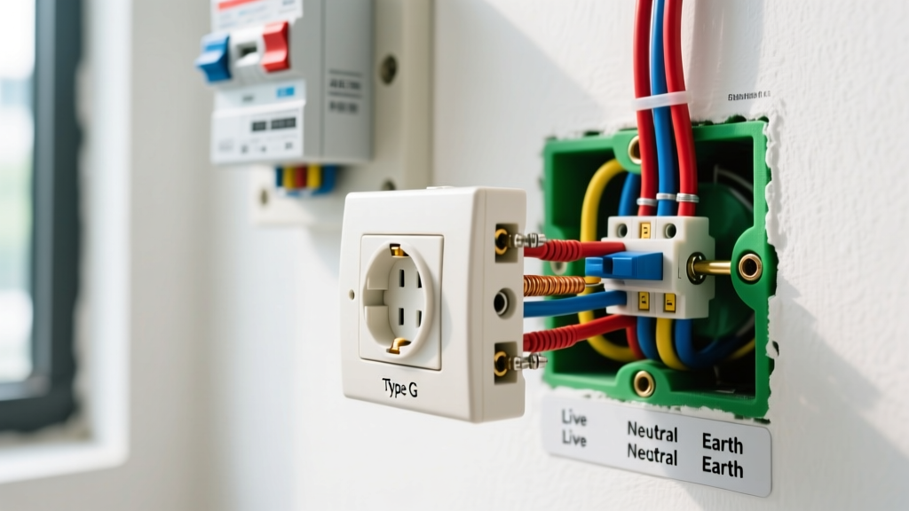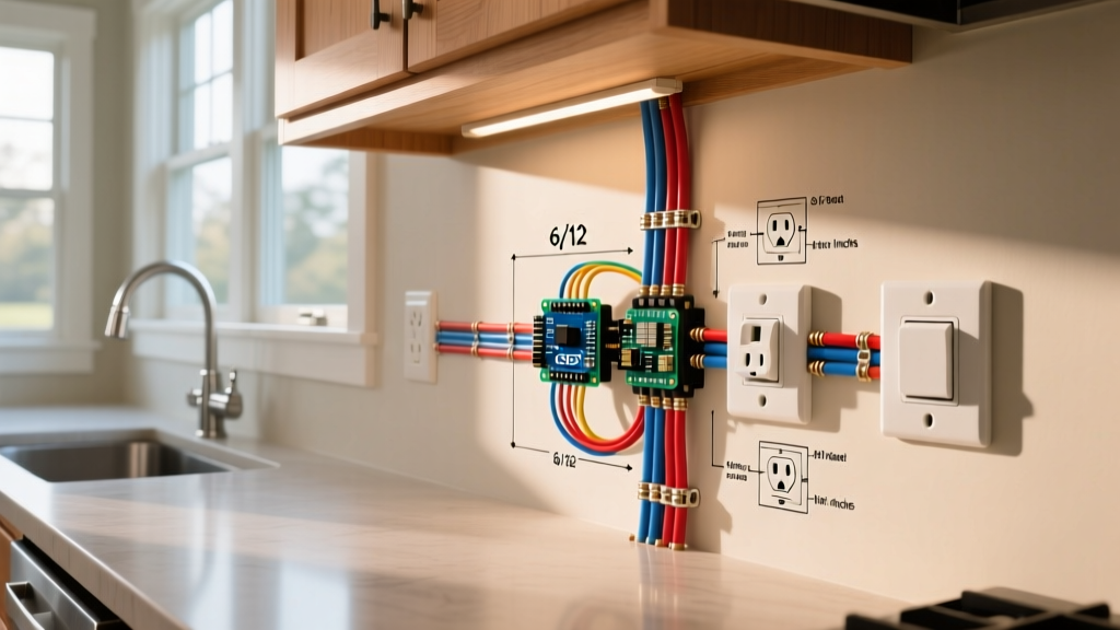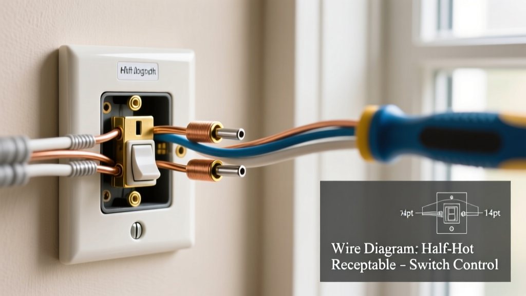

Understanding the Switch for Electrical Outlet Concept
Wiring a wall switch to control a standard plug-in receptacle is one of the most common residential electrical tasks. Whether you are finishing a basement, upgrading a living room without overhead lighting, or installing a dedicated switch for a kitchen garbage disposal, understanding how to configure a switch for electrical outlet control is essential. In modern residential wiring, this typically falls into two distinct categories: the half-hot (split-wired) receptacle and the fully switched receptacle.
As of 2026, the National Electrical Code (NEC) continues to evolve regarding Arc-Fault Circuit Interrupter (AFCI) protection and lighting outlet requirements. This guide breaks down the exact wiring scenarios, component specifications, and code compliance metrics you need to execute these installations safely and effectively.
Why Use a Switched Receptacle? (NEC 210.70 Context)
Under NEC Article 210.70, habitable rooms in dwelling units must have at least one lighting outlet controlled by a wall switch. In rooms like living areas or bedrooms where builders often omit hardwired ceiling fixtures to save costs, a switched receptacle satisfies this code requirement. By wiring a switch to control a floor lamp via a standard duplex outlet, you achieve code compliance while maintaining design flexibility.
Scenario 1: The Half-Hot (Split-Wired) Receptacle
The half-hot receptacle is the industry standard for living rooms and bedrooms. In this configuration, the top half of the duplex outlet is controlled by a wall switch (for a lamp), while the bottom half remains constantly hot (for a vacuum cleaner, phone charger, or TV).
Step-by-Step Split-Wiring Procedure
- Run 3-Wire Cable: You must use a 3-conductor cable (e.g., 14/3 NM-B for 15A circuits or 12/3 NM-B for 20A circuits) between the switch box and the outlet box. The black wire carries the constant hot, the red wire carries the switched hot, the white wire is the shared neutral, and the bare copper is the ground.
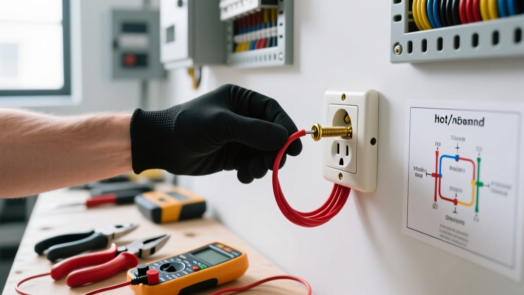
- Break the Brass Tab: This is the most critical step. On the side of the receptacle where the brass (hot) screws are located, there is a small metal connecting fin between the top and bottom screws. Use a pair of needle-nose pliers to bend this tab back and forth until it snaps off. Do not break the silver tab on the neutral side. Breaking the brass tab isolates the top and bottom receptacles electrically.
- Terminate the Neutrals and Grounds: Connect the white neutral wires to the silver screws using the side-wiring method (avoid backstabbing). Pigtail the bare copper ground wires and attach them to the green grounding screw on the receptacle yoke.
- Wire the Hot Legs: Connect the black (constant hot) wire to one brass screw, and the red (switched hot) wire to the other brass screw. While electrically it does not matter which brass screw gets the black or red wire, standard practice dictates placing the constant hot on the bottom and the switched hot on the top.
Pro-Tip for 2026 Installations: Always use the side-wire (screw terminal) or back-wire (screw-clamp) termination methods. The push-in 'backstab' connections rely on weak internal spring contacts that are notorious for causing high-resistance faults and intermittent power loss over time.
Scenario 2: Fully Switched Receptacles
A fully switched receptacle means both the top and bottom halves of the outlet are controlled simultaneously by a single wall switch. This scenario is highly common in kitchens for garbage disposals, in bathrooms for vanity lighting plugs, or on exterior patios for holiday lighting.
Unlike the split-wired scenario, you only need standard 2-wire cable (14/2 or 12/2 NM-B). The switch simply interrupts the hot leg (black wire) before it reaches the receptacle. The brass connecting tab on the receptacle remains intact. The white neutral wire bypasses the switch entirely and runs directly from the panel (or upstream outlet) to the receptacle's silver terminal.
Materials & Component Breakdown (2026 Pricing)
Choosing commercial-grade or high-quality residential components prevents premature failure. Below is a breakdown of standard materials required for a 15-Amp split-wired circuit installation.
| Component | Recommended Model / Spec | Est. Cost (2026) | Application Notes |
|---|---|---|---|
| 15A Duplex Receptacle | Leviton 5262-SW (Commercial Grade) | $3.50 | Features robust internal contacts and easy-break tabs. |
| 15A Single Pole Switch | Leviton 1451 (Commercial Toggle) | $2.80 | Heavy-duty contacts prevent arcing on inductive loads. |
| 14/3 NM-B Cable | Southwire Romex SIMpull (50 ft) | $32.00 | Required for split-wired circuits (Black, Red, White, Ground). |
| 15A AFCI Breaker | Square D HOM115CAFIC | $48.00 | Mandatory for bedroom/living room circuits per NEC 210.12. |
NEC Code Compliance & AFCI Requirements
When installing a switch for an electrical outlet in dwelling units, you must adhere to strict safety codes. According to OSHA electrical safety guidelines and the latest NEC updates, virtually all 120-volt, 15- and 20-ampere branch circuits supplying outlets in family rooms, dining rooms, living rooms, parlors, libraries, dens, sunrooms, recreation rooms, closets, hallways, and similar areas must be protected by a Combination-Type Arc-Fault Circuit Interrupter (AFCI).
If you are upgrading an older home that previously utilized standard breakers for switched outlets, you must replace the breaker in the main panel with an AFCI breaker, or install an AFCI receptacle at the first outlet in the circuit run. Standard GFCI protection is not a substitute for AFCI protection in these dry, habitable areas.
Smart Alternatives: Bypassing the Hardwired Switch
If your goal is simply to control a lamp via a smartphone or voice assistant, and you want to avoid running 14/3 NM-B cable through finished drywall, smart plugs offer a zero-wiring alternative. Devices like the Kasa EP25 or Wyze Plug allow you to schedule lighting or trigger it via motion sensors. The U.S. Department of Energy notes that smart plugs can also help mitigate 'phantom load' energy drain by completely cutting power to electronics when not in use. However, for new construction or gut-renovations, hardwired switched receptacles remain the gold standard for reliability and code compliance.
Troubleshooting Common Wiring Failures
- Both Halves are Switched: You forgot to break the brass connecting tab on the hot side of the receptacle. The switch is feeding both the top and bottom terminals simultaneously.
- Neither Half Works: Check for a tripped AFCI breaker. Combination AFCI breakers are highly sensitive and will trip if the neutral and ground wires touch anywhere downstream of the panel, or if the shared neutral on a multi-wire branch circuit is improperly configured.
- Switch Works, But Lamp Flickers: This usually indicates a loose connection. If you used the backstab push-in holes on the receptacle, the internal spring has likely lost tension. Move the wire to the side-screw terminal and torque it down firmly.
- Constant Hot is Dead, Switched Works: You likely have a broken black wire in the 14/3 cable, or the wire nut connection in the switch box has vibrated loose. Verify continuity with a multimeter.
Frequently Asked Questions
Can I use a 3-way switch to control an electrical outlet?
Yes. You can wire a half-hot receptacle to be controlled by two different 3-way switches (e.g., at the top and bottom of a staircase). This requires running 14/3 cable between the two 3-way switches and utilizing the red and black travelers to feed the switched hot down to the receptacle's isolated brass terminal.
Do I need to pigtail the ground wire?
Absolutely. NEC code requires that the grounding continuity must not be broken by removing a device. You must splice all incoming and outgoing bare copper ground wires together with a wire nut, and run a single 6-inch pigtail to the green grounding screw on the receptacle yoke.
What happens if I break the silver (neutral) tab by mistake?
If you break the silver tab but only have one white neutral wire connected, either the top or bottom half of the outlet will not work, as the neutral return path is severed for the isolated half. If you are not doing a multi-wire branch circuit (MWBC) with two separate neutrals, the silver tab must always remain intact.