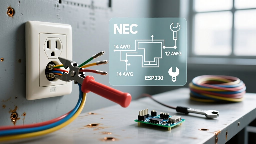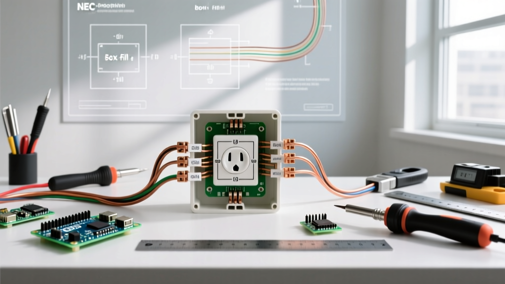

Installing or replacing a standard US electrical outlet (technically known as a NEMA 5-15R receptacle) is one of the most common residential electrical tasks. However, despite its ubiquity, improper installation remains a leading cause of electrical fires and equipment damage. According to the National Fire Protection Association (NFPA), electrical malfunctions account for tens of thousands of home fires annually, many stemming from loose terminal connections or reversed polarity.
This comprehensive, step-by-step guide will walk you through the exact procedures used by licensed electricians to wire a 120-volt, 15-amp US electrical outlet. We will cover tool selection, National Electrical Code (NEC) compliance, precise torque specifications, and advanced wiring techniques to ensure a safe, long-lasting installation.
Essential Tools and Materials for Outlet Installation
Before beginning, gather professional-grade tools. Relying on improvised tools often leads to stripped screws, damaged wire insulation, or unsafe connections.
- Receptacle: Leviton T5320-W (15A, 125V, Tamper-Resistant, Duplex). Cost: ~$4.50. Ensure it is marked "TR" for Tamper-Resistant, as mandated by NEC Article 406.12 for all dwelling units.
- Wire Strippers: Klein Tools 11055 (strips 10-18 AWG solid/stranded). Cost: ~$28.00.
- Non-Contact Voltage Tester & Multimeter: Fluke 117 True-RMS Multimeter and Fluke 2AC VoltAlert. Cost: ~$220 combined. Never rely solely on a non-contact tester.
- Torque Screwdriver: Milwaukee 48-22-9003 or Klein Tools 691. Cost: ~$120. Crucial for meeting modern NEC 110.14(D) torque requirements.
- Screwdrivers: Insulated #2 Phillips and 1/4-inch slotted (e.g., Klein Tools 32500).
- Lineman's Pliers & Needle-Nose Pliers: For bending J-hooks and twisting pigtails.
Anatomy of a Standard US Electrical Outlet
A standard US electrical outlet operates on a 120V split-phase system. Understanding the terminal layout is critical for correct wiring.
Terminal Identification
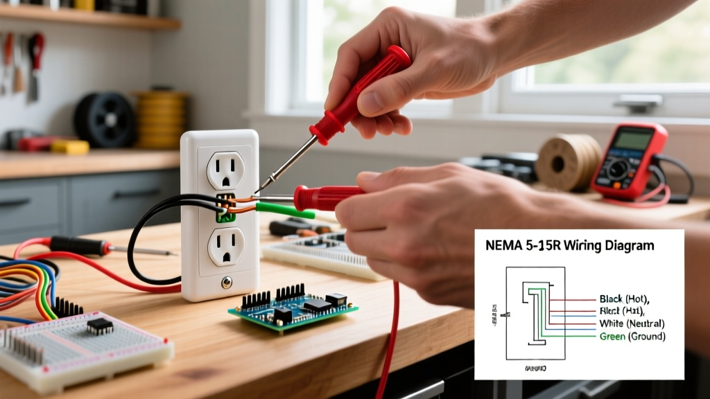
- Brass Screws (Hot/Line): Connects to the black (or red) insulated wire. This carries the 120V current from the breaker panel.
- Silver Screws (Neutral): Connects to the white insulated wire. This completes the circuit back to the panel.
- Green Screw (Ground): Connects to the bare copper or green insulated wire. This provides a safe path for fault currents.
Expert Insight: The Electrical Safety Foundation International (ESFI) strongly emphasizes the use of Tamper-Resistant (TR) receptacles. TR outlets feature internal spring-loaded shutters that only open when equal pressure is applied to both slots simultaneously, preventing children from inserting foreign objects. As of the 2026 NEC cycle, TR receptacles are strictly required in all new residential installations and replacements.
Step-by-Step Wiring Process
Step 1: Power Isolation and Verification
Turn off the circuit breaker controlling the outlet. Use a non-contact voltage tester to check for power, then insert a multimeter's probes into the outlet slots (Hot to Neutral, Hot to Ground) to verify 0.0V. Never skip the multimeter verification step.
Step 2: Wire Preparation and Stripping
Inspect the wires for nicks or corrosion. If the existing wire is damaged, cut it back to healthy copper. Using your Klein Tools 11055 wire strippers, strip exactly 3/4 inch (19mm) of insulation from the black, white, and ground wires. Stripping too little will cause the insulation to bind under the screw head; stripping too much will leave exposed, live copper outside the terminal.
Step 3: Forming the J-Hook (Side-Wiring)
Using needle-nose pliers, bend the stripped end of each wire into a smooth, clockwise J-hook. The clockwise direction is vital: as you tighten the screw clockwise, the loop will naturally close and pull tighter around the screw shaft. A counter-clockwise loop will be pushed out from under the screw head as it tightens, creating a severe fire hazard.
Step 4: Making the Connections
- Ground First: Loop the bare/green wire around the green grounding screw. Tighten securely.
- Neutral Second: Loop the white wire around one of the silver screws. Tighten securely.
- Hot Last: Loop the black wire around one of the brass screws. Tighten securely.
Step 5: Torque Verification
Modern electrical codes require terminals to be tightened to the manufacturer's specified torque. For most standard Leviton and Hubbell 15A/20A receptacles, the required torque is 14 in-lbs (1.58 Nm). Use your calibrated torque screwdriver to click at exactly 14 in-lbs. This prevents "cold flow" loosening over time and prevents thermal expansion damage from over-tightening.
Step 6: Wrap and Secure
Wrap the sides and back of the receptacle with high-quality electrical tape (e.g., 3M Super 33+). Cover the terminal screws and exposed ground wires. This prevents accidental short circuits against a metal junction box. Carefully fold the wires into the box using an accordion fold (ground in back, neutrals in middle, hots in front), then secure the receptacle to the box using the provided 6-32 mounting screws.
Side-Wiring vs. Back-Wiring: Which is Better?
Many modern US electrical outlets offer both side-wiring (J-hook) and back-wiring (screw-clamp) options. It is crucial to understand the difference between back-wiring and the older, dangerous "push-in" (stab-in) connections.
| Connection Type | Mechanism | Wire Gauge Accepted | Reliability & Code Status |
|---|---|---|---|
| Side-Wiring (J-Hook) | Wire loops around the screw head. | 14 & 12 AWG Solid | Excellent. The traditional standard. Requires proper clockwise looping and torque. |
| Back-Wiring (Screw-Clamp) | Wire inserted into a hole; screw tightens a internal clamp plate. | 14 & 12 AWG Solid/Stranded | Superior. Preferred by commercial electricians. Larger contact area, faster installation, no J-hook required. |
| Push-In (Stab-In) | Wire pushed into a hole; spring-metal barb grips it. | 14 AWG Solid ONLY | Poor. High failure rate due to thermal cycling and arcing. Banned for 12 AWG wire. Avoid entirely. |
Pro Tip: If your receptacle features screw-clamp back-wiring (identified by a pressure plate that moves when you turn the screw), use it. Simply strip the wire to the gauge marker on the back of the device (usually 5/8 inch), insert it straight into the back hole, and torque the screw to 14 in-lbs. This is faster and often provides a more reliable connection than a hand-bent J-hook.
Handling Multiple Wires and Pigtailing
If the junction box contains two sets of cables (one bringing power in, one taking power to the next outlet downstream), you have two choices:
- Double-Tapping (Not Recommended): Placing two wires under a single screw head. This is a violation of NEC 110.14(A) unless the terminal is explicitly identified for the purpose.
- Using the Second Set of Screws: Most duplex outlets have two brass and two silver screws. You can connect the incoming wires to the top screws and the outgoing wires to the bottom screws. Note: You must break the brass connecting tab on the hot side only if you are splitting the outlet for a switched half-hot configuration. Otherwise, leave the tabs intact.
- Pigtailing (Best Practice): Connect all incoming and outgoing black wires together with a wire nut (e.g., Ideal Wing-Nut Yellow), adding a 6-inch black "pigtail" wire. Connect the single pigtail to the receptacle's brass screw. Repeat for the white neutral wires and bare ground wires. This ensures that if the receptacle is removed for servicing, the downstream circuit is not interrupted, satisfying NEC 300.13(B) for neutral continuity.
Wire Gauge and Breaker Sizing Matrix
Installing the correct US electrical outlet requires matching the receptacle rating to the wire gauge and breaker size. Mismatching these components is a severe fire hazard.
| Breaker Size | Wire Gauge (Copper) | Receptacle Type Required | NEMA Configuration |
|---|---|---|---|
| 15 Amp | 14 AWG (or 12 AWG) | 15A Receptacle | NEMA 5-15R |
| 20 Amp | 12 AWG (14 AWG is illegal) | 15A or 20A Receptacle | NEMA 5-15R or 5-20R |
Note: A 20A receptacle (NEMA 5-20R) features a T-shaped neutral slot to accept 20A plugs. You can legally install standard 15A receptacles on a 20A circuit, provided it is a multi-outlet branch circuit serving multiple devices, per NEC 210.21(B)(1).
Common Wiring Mistakes and Troubleshooting
Even experienced DIYers make errors. Use this troubleshooting matrix to identify and correct common issues before energizing the circuit.
| Symptom / Tester Reading | Probable Cause | Correction |
|---|---|---|
| Reversed Polarity (Hot/Neutral swapped) | Black wire on silver screw, white wire on brass screw. | Swap the wires. Hot (black) must always be on the brass screw. |
| Open Ground | Ground wire disconnected, broken, or not bonded to the box. | Verify ground continuity. Ensure the bare wire is tightly secured to the green screw. |
| Hot/Ground Reversed | Black wire on green screw, bare wire on brass screw. | Extremely dangerous. Immediately disconnect power and re-terminate. |
| Breaker Trips Instantly | Short circuit (Hot touching Ground or Neutral) or wire nut failure. | Inspect junction box for exposed copper touching the metal box or other wires. |
Final Inspection and Energizing
Once the outlet is secured and the wall plate is installed, turn the breaker back on. Use a standard 3-light receptacle tester (e.g., Gardner Bender GRT-501) to verify correct wiring. The tester should display two amber lights, indicating "Correct Wiring." Follow up with your multimeter to confirm exactly 120V (+/- 5%) between the hot and neutral slots, and 120V between hot and ground.
For further reading on residential electrical safety and code compliance, consult the Occupational Safety and Health Administration (OSHA) electrical safety guidelines and your local authority having jurisdiction (AHJ), as local amendments to the NEC may apply in your specific municipality.
By adhering to precise stripping lengths, utilizing clockwise J-hooks or screw-clamp back-wiring, and strictly applying 14 in-lbs of torque, your US electrical outlet installation will be safe, code-compliant, and built to last for decades.