
Decoding the Wiring Diagram for a 3-Way Light Switch
Controlling a single lighting fixture from two separate locations is a staple of modern residential electrical design, commonly found in stairwells, long hallways, and large living areas. However, executing a safe and reliable installation requires more than just a basic understanding of the circuit. This comprehensive tool and material guide breaks down the exact wiring diagram for a 3-way light switch, pairing the electrical topology with the specific, professional-grade tools and materials required to complete the job to 2026 National Electrical Code (NEC) standards.
The Anatomy of a 3-Way Switch
Before touching any tools, you must understand the terminal layout of a standard 3-way switch (such as the Leviton Decora 5603-2W or Lutron Claro CA-3PS). Unlike a single-pole switch, a 3-way switch does not have 'ON' and 'OFF' markings. Instead, it features three main terminal screws plus a ground:
- Common Terminal (Black Screw): This is the critical pivot point. On the first switch, it connects to the incoming hot (line) power. On the second switch, it connects to the outgoing hot (load) feeding the light fixture.
- Traveler Terminals (Two Brass Screws): These carry the alternating current between the two switches. The two traveler wires from the 3-conductor cable connect here. Their placement on the brass screws is interchangeable.
- Ground Terminal (Green Screw): Connects to the bare copper or green insulated equipment grounding conductor.
The Standard Topology: Power Entering Switch 1
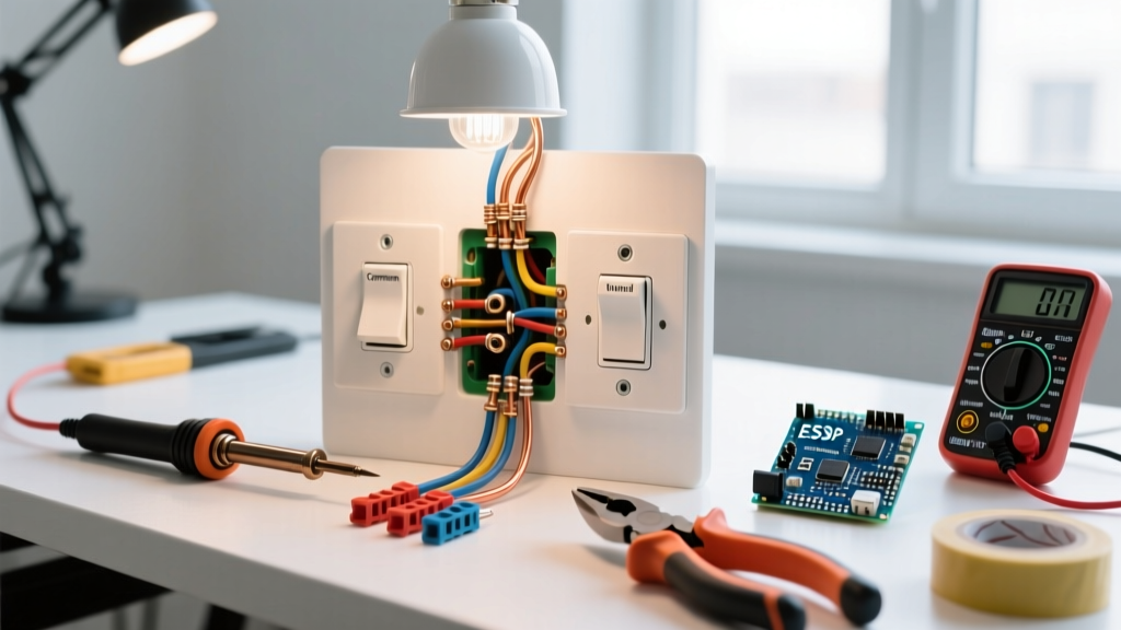
While there are four possible wiring topologies for a 3-way circuit, the most common and easiest to troubleshoot is Power Source ➔ Switch 1 ➔ Switch 2 ➔ Light Fixture. Here is how the wiring diagram maps out in this scenario:
- At Switch 1: The 2-conductor power cable (14/2 or 12/2) enters the box. The bare ground connects to the box and switch. The white neutral wire bypasses the switch and splices directly to the white neutral of the 3-conductor cable heading to Switch 2. The black hot wire connects to the Common (black) screw on Switch 1.
- Between Switches: A 3-conductor cable (14/3 or 12/3) runs between the switch boxes. The red and black wires act as travelers, connecting to the brass screws on both switches. The white wire in this cable serves as a neutral pass-through and must be spliced together with wire nuts or lever connectors.
- At Switch 2: The red and black travelers connect to the brass screws. The white neutral passes through to the light fixture. A 2-conductor cable runs from Switch 2 to the light. The black wire connects to the Common (black) screw on Switch 2 and continues to the black (hot) wire at the light fixture.
Essential Tools for 3-Way Switch Wiring
Using the correct tools prevents damaged conductors, loose connections, and potential fire hazards. Below is the exact toolkit recommended for this specific wiring diagram.
| Tool Category | Recommended Model | Est. Cost | Specific Purpose in 3-Way Wiring |
|---|---|---|---|
| Non-Contact Voltage Tester | Fluke 2AC II VoltAlert | $28.00 | Verifying absence of voltage on line, load, and travelers before touching terminals. |
| Wire Strippers | Klein Tools 11063W (10-14 AWG) | $24.00 | Stripping NM-B sheathing and precise 3/4-inch insulation removal without nicking copper. |
| Multi-Bit Screwdriver | Klein Tools 32308 | $16.00 | Tightening terminal screws (Phillips #2) and tightening ground clips (Slotted). |
| Cable Ripper | Gardner Bender CP-200 | $6.00 | Slitting the PVC jacket of 14/3 NM-B without scoring the internal wire insulation. |
| Tongue & Groove Pliers | Channellock 440 (12-inch) | $35.00 | Tightening internal cable clamps in metal or heavy-duty PVC junction boxes. |
Pro Tip: Never use a standard utility knife to strip the outer PVC jacket of a 14/3 or 12/3 Romex cable. Scoring the internal red, black, or white insulation creates a micro-fissure that can lead to arcing and thermal failure under load. Always use a dedicated cable ripper.
Materials & Wire Sizing Guide
The materials you select dictate the amperage capacity and longevity of your 3-way circuit. In 2026, the standard for residential lighting remains 15-amp circuits using 14 AWG wire, though 20-amp circuits with 12 AWG wire are increasingly common in modern builds to accommodate future smart-home loads.
| Material | Specification | Application / NEC Rule |
|---|---|---|
| 2-Conductor Cable | Southwire 14/2 NM-B (or 12/2) | Used for Power-to-Switch 1, and Switch 2-to-Light runs. |
| 3-Conductor Cable | Southwire 14/3 NM-B (or 12/3) | Required between Switch 1 and Switch 2 to provide two travelers and a neutral. |
| Wire Connectors | Wago 221-413 Lever Nuts | 3-port lever connectors. Superior to twist-on nuts for solid copper 14/12 AWG splices. |
| Switches | Leviton 5603-2W (15A) or 5203-W (20A) | Standard toggle or Decora rocker 3-way switches. Ensure amp rating matches breaker. |
| Ground Pigtails | 14 AWG Bare Copper | Required to bond the metal box, the incoming ground, and the switch ground screw. |
NEC Compliance & The Neutral Requirement
When reviewing any wiring diagram for a 3-way light switch, you must account for NEC Article 404.2(C). This code mandates that a neutral conductor must be present at the switch box. Even if you are installing standard mechanical 3-way switches today, you must run the 3-conductor cable (which includes the white neutral wire) between the switches and cap the neutral with a Wago lever nut or wire nut. This ensures that if a future homeowner upgrades to a smart switch (like the Lutron Caseta PD-5S-DV), the required neutral is already available in the box without requiring a costly rewiring project.
Step-by-Step Execution & Pro Tips
- Kill and Verify: Turn off the 15A or 20A breaker. Use the Fluke 2AC II to test the incoming black wire, the travelers, and the load wire. Test the tester on a known live circuit first to ensure the battery is functional.
- Prep the Conductors: Strip exactly 3/4-inch of insulation from the ends of the solid copper wires for standard side-wiring terminal screws. If using Wago 221 lever nuts for your splices, strip exactly 11mm (approx. 1/2-inch) using the built-in gauge on the Klein 11063W strippers.
- Make Up the Grounds: In metal boxes, bond the bare copper grounds to the box using a green grounding screw, then pigtail to the switch's green screw. In non-metallic (PVC) boxes, simply bundle all bare grounds together and pigtail to the switch.
- Splice the Neutrals: Group all white neutral wires together. Do not attach them to any terminal on a standard mechanical 3-way switch. Secure them with a Wago 221-413 connector.
- Wire the Travelers: Connect the red and black wires of the 14/3 cable to the two brass screws on both switches. Polarity between the two brass screws does not matter.
- Connect the Commons: Attach the incoming hot (black) to the black screw on Switch 1. Attach the outgoing load (black) to the black screw on Switch 2.
- Final Torque: Tighten all terminal screws firmly. A loose connection on a traveler wire will cause voltage drop, flickering, and eventual thermal melting of the switch housing.
Troubleshooting Common Failure Modes
If your installation fails to operate correctly, the issue almost always stems from a misinterpretation of the wiring diagram. Here are the most common edge cases:
- Light works on Switch 1, but Switch 2 does nothing: You have likely connected the outgoing load wire to a brass traveler screw on Switch 2 instead of the black common screw. The circuit requires the load to be on the common terminal to complete the path.
- The light works, but only when both switches are in the 'UP' position: This indicates a crossed traveler. Ensure that the red and black travelers are isolated from the common terminals and that no neutral wire has been accidentally used as a traveler.
- Breaker trips immediately upon throwing the switch: You have created a direct short. This usually happens when the incoming hot line is accidentally wired to a traveler screw, and the corresponding traveler at the other switch is wired to a neutral or ground.
Authoritative References
For further reading on electrical safety and code compliance, consult the following authoritative resources:
- National Fire Protection Association (NFPA) - National Electrical Code: The definitive source for NEC articles, including Article 404 regarding switch installation and neutral requirements.
- Occupational Safety and Health Administration (OSHA) - Electrical Safety: Comprehensive guidelines on lockout/tagout procedures and safe verification of de-energized circuits before beginning any DIY or professional wiring project.