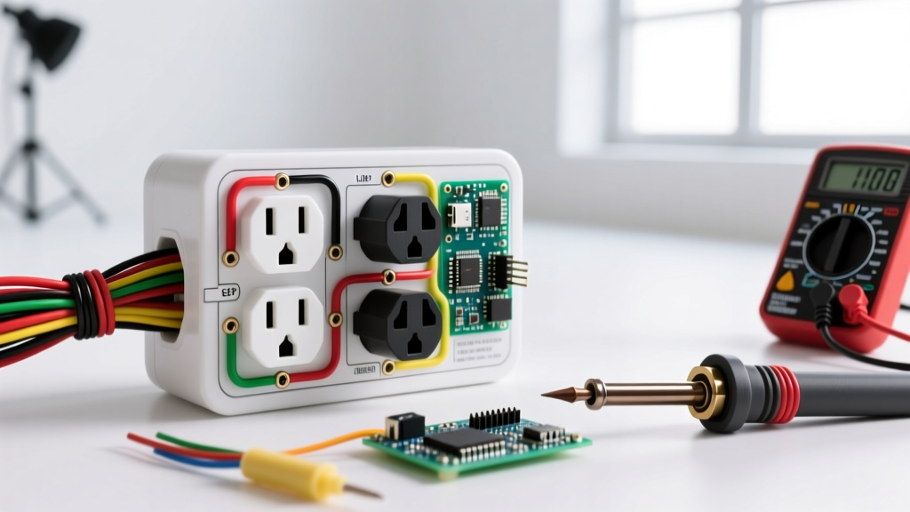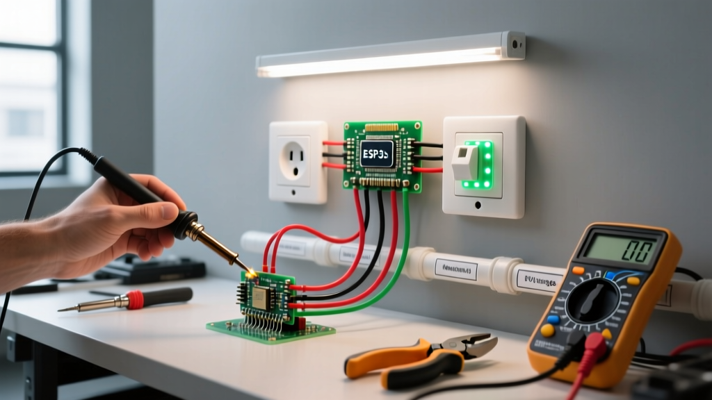

Understanding the Illuminated Electrical Outlet Sign
In modern electrical installations, visual confirmation of live power is no longer just a luxury—it is a critical safety and operational requirement. An electrical outlet sign, commonly referred to as a hardwired LED status indicator or pilot light sign, provides immediate visual feedback that a specific receptacle circuit is energized. As of 2026, with the massive surge in Level 2 EV home chargers, high-draw workshop equipment, and dedicated server rack circuits, knowing exactly when a 120V or 240V outlet is live can prevent catastrophic arc flashes and equipment damage.
Unlike standard plug-in neon testers, a hardwired electrical outlet sign is permanently mounted in a junction box or integrated into the receptacle cover plate. It draws minimal current (typically under 5mA) and utilizes high-efficiency LEDs or neon bulbs rated for the exact voltage of the circuit. This guide will walk you through the step-by-step installation of a surface-mount LED indicator sign adjacent to a dedicated receptacle, ensuring compliance with modern safety standards.
Why Install a Hardwired Status Sign?
While a standard multimeter can verify voltage, it requires active testing. An electrical outlet sign offers passive, continuous monitoring. This is particularly vital in three scenarios:
- EV Charging Stations: Confirming the 240V/50A dedicated circuit is live before plugging in a vehicle, preventing contactor burnout.
- Server Rooms & IT Closets: Identifying critical branch circuits that are tied to UPS or backup generator systems.
- Industrial Workshops: Warning personnel that a 3-phase or high-amperage single-phase outlet is energized, satisfying OSHA visual warning recommendations.
Tools, Materials, and Cost Breakdown
Before beginning, gather the necessary components. Using high-quality, UL-listed materials is non-negotiable for permanent installations.
| Item | Specification / Model Example | Estimated Cost (2026) |
|---|---|---|
| LED Indicator Sign | Schneider Electric Harmony XB4 (120V/240V AC) | $18.00 - $35.00 |
| Junction Box | 4x4x2.125 inch Steel Box with FS Cover | $8.50 - $12.00 |
| Wire / Cable | 12/2 NM-B (for 20A circuits) or THHN in conduit | $0.75 / ft |
| Connectors | Wago 221 Lever-Nuts (3-Port) | $6.00 / pack |
| Voltage Tester | Fluke 1AC-II VoltAlert (CAT III 1000V) | $35.00 |
| Torque Screwdriver | Klein Tools 6-Inch Torque (set to 14 in-lbs) | $45.00 |
120V vs. 240V Wiring Configurations
The wiring methodology changes depending on the voltage of the outlet you are monitoring. Never wire a 120V rated LED sign directly across two hot legs of a 240V circuit, as it will instantly destroy the internal resistor and create a short-circuit hazard.
| Circuit Type | Sign Voltage Rating | Wiring Connection | Breaker Requirement |
|---|---|---|---|
| Standard 120V (15A/20A) | 120V AC LED | Hot (Black) to Line 1, Neutral (White) to Line 2 | Single-Pole 15A/20A |
| Split-Phase 240V (EV/Welder) | 240V AC LED | Hot 1 (Black) to Line 1, Hot 2 (Red) to Line 2 | Dual-Pole 30A-50A |
| 120/240V Multi-Wire | 120V AC LED | Hot (Black) to Line 1, Neutral (White) to Line 2 | Handle-Tied Dual-Pole |
Step-by-Step Installation Guide
Step 1: Lockout/Tagout (LOTO) and Verification
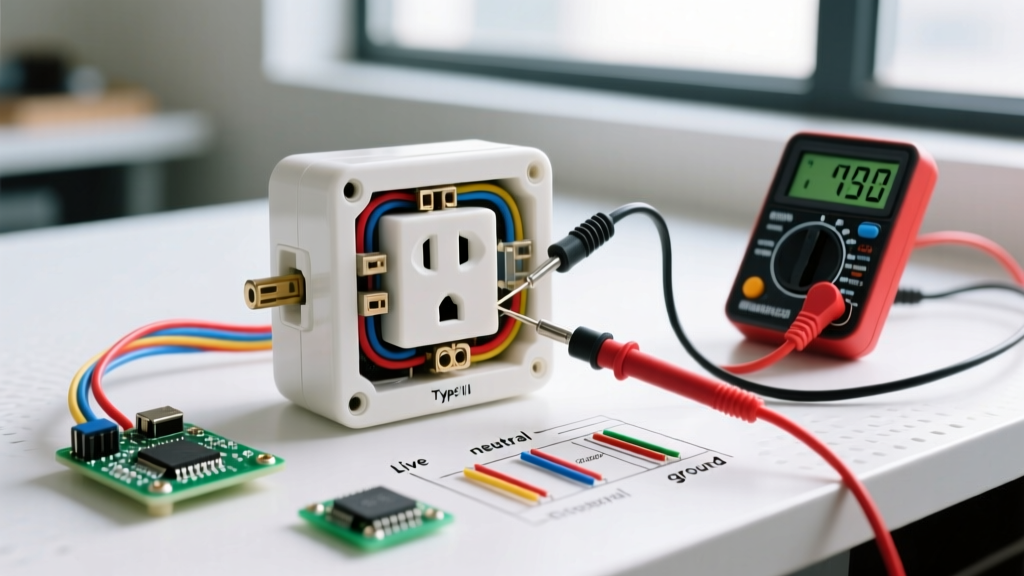
Never rely on a wall switch or a smart breaker app to confirm a circuit is dead. Navigate to your main electrical panel and switch off the breaker controlling the target outlet. Apply a physical Lockout/Tagout device to the breaker panel. Using your Fluke 1AC-II or a CAT-III rated digital multimeter, test the target outlet. Insert the probes into the hot-neutral and hot-ground slots to verify zero voltage. For 240V outlets, test across both hot slots as well.
Step 2: Mounting the Junction Box
If your electrical outlet sign is a panel-mount style, you will need a dedicated junction box mounted adjacent to the receptacle. Use a stud finder to locate a wall cavity next to the existing outlet. Cut a 4-inch square hole in the drywall and mount a 4x4x2.125-inch steel junction box using Madison straps or direct-to-stud screws. Ensure the box edge is flush with the drywall surface to meet National Electrical Code (NEC) Article 314.20 requirements for box accessibility.
Step 3: Routing the Power Feed
You must pull power from the load side of the existing receptacle or directly from the circuit's junction point. Turn off the power again if you had to turn it on for testing. Remove the existing receptacle from its box. If you are using 12/2 NM-B cable, strip back 3/4 inch of insulation from the black, white, and bare copper wires. Feed the cable through a 1/2-inch NM cable connector into the new sign junction box, securing it tightly to the box knockout.
Step 4: Pigtailing and Terminating
Do not daisy-chain the wires directly through the sign's terminals unless the manufacturer explicitly allows feed-through. Instead, use pigtails.
1. Connect the incoming ground wire, the receptacle ground, and a 6-inch green ground pigtail using a Wago 221 lever-nut.
2. Connect the incoming white neutral, the receptacle neutral, and a 6-inch white pigtail.
3. Connect the incoming black hot, the receptacle hot, and a 6-inch black pigtail.
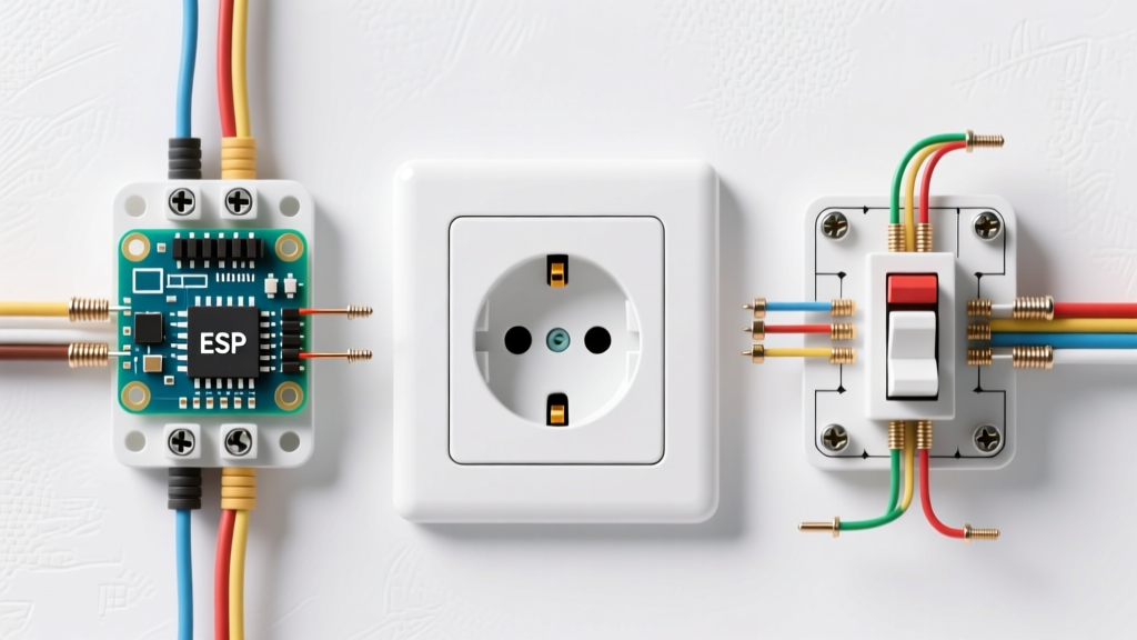
Route the black and white pigtails into the new sign junction box. Connect the black pigtail to the 'L1' terminal on the LED indicator sign, and the white pigtail to the 'L2' or 'N' terminal. Use a calibrated torque screwdriver set to the manufacturer's specification (typically 12 to 14 in-lbs for standard brass terminal screws) to prevent loose connections that cause arcing.
Step 5: Securing the Sign and Final Testing
Carefully fold the wires into the back of the junction box, ensuring no bare ground wires are touching the hot terminals. Mount the electrical outlet sign faceplate to the box using the provided 6-32 machine screws. Remove the LOTO device, restore power at the main panel, and observe the sign. The LED should illuminate instantly, confirming the outlet is energized.
NEC Compliance and Safety Standards
Code Watch: According to the NEC and guidelines outlined by OSHA's electrical safety standards, any permanently installed indicator must be rated for the environment it occupies. If your electrical outlet sign is installed in a garage, outdoor workshop, or damp location, the indicator housing and junction box must carry a NEMA 3R or 4X rating to prevent moisture ingress and subsequent short circuits.
Furthermore, Article 110.12 of the NEC mandates 'mechanical execution of work.' This means your pigtails must be neat, wires must not be jammed into the box, and the sign must sit flush against the wall. Sloppy wiring inside the indicator box is a common reason for failed municipal inspections.
Troubleshooting Common LED Sign Failures
If your newly installed electrical outlet sign fails to illuminate, or behaves erratically, consult this troubleshooting matrix before tearing into the wall:
- Ghost Voltage / Faint Flickering: If the LED glows faintly when the breaker is off, you are likely experiencing capacitive coupling or 'ghost voltage' from adjacent live wires in the same conduit. While harmless to the sign, it can be confusing. Solution: Ensure your neutral is bonded correctly at the main panel and consider adding a 10k-ohm bleeder resistor across the sign terminals.
- Sign Burns Out Immediately: You have likely wired a 120V rated LED across a 240V split-phase circuit. Check the voltage rating stamped on the side of the indicator housing. Replace the unit with a 240V AC specific model.
- Intermittent Blinking: This is almost always caused by a loose neutral connection or a failing backstab connector on the adjacent receptacle. Remove all backstabbed wires on the main receptacle and move them to the side terminal screws, torquing them to 14 in-lbs.
For deeper technical schematics on indicator lamp wiring, resources like Electrical Technology provide excellent visual diagrams for both single-phase and three-phase indicator setups. By following these precise installation steps, your electrical outlet sign will provide years of reliable, life-saving visual feedback.