
Pre-Installation: Code, Load, and Material Planning
Learning how to add an electrical outlet to an existing wall is one of the most practical DIY electrical upgrades you can undertake. Whether you are eliminating an extension cord hazard behind a wall-mounted TV or adding a dedicated charging station in a home office, extending an existing 120V branch circuit requires strict adherence to the National Electrical Code (NEC). According to the National Fire Protection Association (NFPA), improper receptacle wiring and overloaded circuits remain leading causes of residential electrical fires.
Before cutting any drywall, you must verify that the existing circuit has the capacity to handle the additional load. A standard 15-amp circuit can safely handle 1,800 watts, while a 20-amp circuit handles 2,400 watts. However, under the NEC 80% continuous load rule, you should only plan for 1,440 watts (15A) or 1,920 watts (20A) if the connected devices will run for three hours or more.
2026 Material and Tool Cost Breakdown
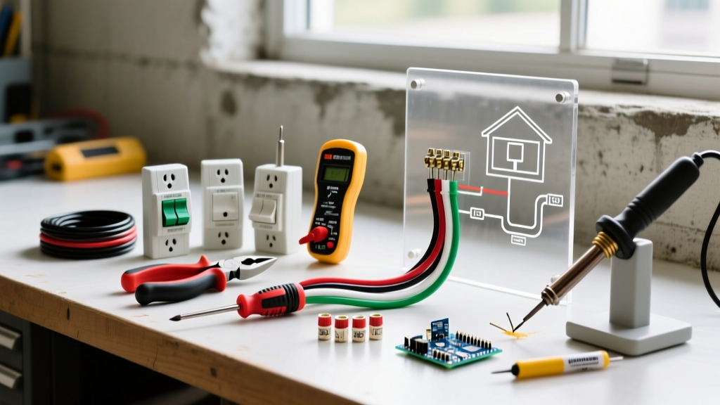
Below is a realistic cost estimate for a standard 12 AWG, 20-amp receptacle extension using premium, contractor-grade components available in 2026.
| Item | Specific Model / Brand | Estimated Cost (2026) |
|---|---|---|
| NM-B Cable (25 ft) | Southwire 12/2 SIMpull Romex | $26.50 |
| Old-Work Box (1-Gang) | Carleton B120R 22.5 cu in. | $3.85 |
| Receptacle | Leviton T5362-W 20A Tamper-Resistant | $4.10 |
| Fish Sticks | Klein Tools 56350 Fiberglass Kit | $48.00 |
| Torque Screwdriver | Klein Tools 650-4 (Calibrated) | $65.00 |
| Receptacle Tester | Klein Tools RT250 GFCI/AFCI Tester | $34.95 |
Step 1: Verifying Circuit Capacity and AFCI/GFCI Rules
The first physical step is identifying a suitable upstream receptacle or junction box to tap into. You cannot extend a circuit that serves small-appliance kitchen counters, bathrooms, or laundry rooms, as NEC Article 210.52 restricts these to dedicated circuits.
Furthermore, you must evaluate Arc-Fault (AFCI) and Ground-Fault (GFCI) requirements. If you are adding an outlet in a bedroom, living room, or hallway, the upstream breaker must be an AFCI breaker. If the new outlet is within 6 feet of a water source, in a garage, or outdoors, it must be GFCI protected. The U.S. Consumer Product Safety Commission (CPSC) strongly recommends upgrading older homes with GFCI protection in any area where water and electricity might intersect.
Expert Warning: Never tap into a switch loop to add an outlet. Switch loops often lack a neutral wire, and while older code allowed switch-loop extensions for specific low-draw devices, modern smart home integrations and standard receptacle loads require a dedicated hot, neutral, and ground.
Step 2: Cutting the Drywall and Mounting the Box
For retrofits in finished walls, you will use an 'old-work' (or cut-in) electrical box. The Carleton B120R is a 22.5 cubic-inch PVC box, which provides ample room for box fill calculations.
- Locate Studs: Use a high-quality stud finder (like the Franklin Sensors ProSensor) to ensure your cutout is between studs. Maintain at least 1.25 inches of clearance from the edge of any wooden stud to prevent drywall screws from piercing the cable later.
- Trace the Box: Hold the front flange of the old-work box against the drywall and trace the inner rectangle with a pencil.
- Cut the Opening: Use a drywall keyhole saw or a rotary tool with a drywall bit to cut along the inside of your traced line. Cutting slightly inside the line prevents the box flange from sitting crookedly on the finished wall.
- Mount the Box: Feed the NM-B cable through the integrated clamp of the box, push the box into the wall cavity, and tighten the Phillips-head screws. The internal 'wings' will flip and pull tight against the back of the drywall.
Step 3: Fishing the NM-B Cable
Routing 12/2 NM-B cable through enclosed walls requires patience and the right technique to avoid damaging existing plumbing or HVAC flex ducts.
- Access Points: If you have an unfinished basement or attic directly above/below the target wall, drill a 3/4-inch hole through the top or bottom plate using a flexible right-angle drill attachment (e.g., Greenlee 5388).
- Using Fish Sticks: Attach the cable to the Klein Tools fiberglass fish stick using a pulling eye or heavy-duty electrical tape. Create a smooth, aerodynamic bullet shape with the tape so it doesn't snag on fire blocks or insulation.
- Fire Blocking: If you hit a horizontal fire block inside the wall, you will need to cut a 4x4 inch access hole at the block, drill through it, fish the wire, and patch the drywall afterward. Never blindly force a fish stick, as you could puncture a copper water line or a refrigerant line.
Step 4: Box Fill Calculations and Wire Termination
Before terminating, we must verify NEC Article 314.16 box fill requirements to prevent overcrowding, which causes heat buildup. For 12 AWG wire, each current-carrying conductor counts as 2.25 cubic inches.
- 2 Hot wires (Line and Load) = 4.5 cu in.
- 2 Neutral wires (Line and Load) = 4.5 cu in.
- 1 Ground wire bundle = 2.25 cu in.
- 1 Receptacle device = 4.5 cu in.
- Total Required: 15.75 cubic inches. Our 22.5 cu in. Carleton box passes with plenty of room to spare.
Termination and Torque Specifications
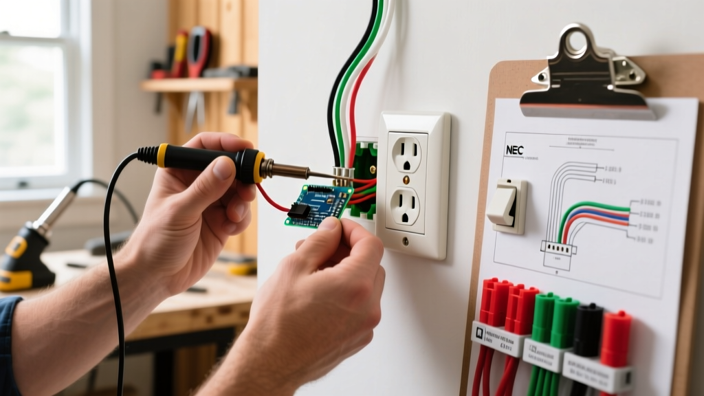
Strip exactly 3/4 inch of insulation from the black and white wires using a wire stripper. Form a J-hook and loop it clockwise around the brass (hot) and silver (neutral) terminal screws. This ensures the screw pulls the wire loop tighter as it is driven in.
As of the 2023 NEC cycle, which is fully enforced in most jurisdictions in 2026, Article 110.14(D) requires that terminal connections be torqued to the manufacturer's specifications. The Leviton T5362-W requires 14 inch-pounds of torque. Use a calibrated torque screwdriver to click at exactly 14 in-lbs. Under-torqued wires cause arcing and fires; over-torqued wires strip the brass threads or shear the screw head.
Pro Tip: Never use the 'backstab' push-in connectors on the rear of the receptacle. While UL-listed, they rely on a small spring-metal wedge that can lose tension over time due to thermal expansion and contraction cycles. Always use the side-binding terminal screws or pigtail the wires with wire nuts and use the screws.
Step 5: Final Testing and Commissioning
Once the receptacle is secured to the box and the wall plate is installed, restore power at the main breaker panel. Do not plug in any expensive electronics until you have verified the wiring integrity.
Insert a Klein Tools RT250 GFCI/AFCI receptacle tester. The LED sequence will instantly diagnose the circuit:
- Correct Wiring: Two yellow lights illuminate.
- Open Ground: Middle yellow and red light. (Indicates the bare copper wire is disconnected or broken upstream).
- Reverse Polarity: Left yellow and red light. (Indicates hot and neutral are swapped—a severe shock hazard).
- Open Neutral: Right yellow light only. (Indicates the white wire is not making contact).
Troubleshooting Common Wiring Faults
If your tester indicates a fault, turn the breaker back off immediately and investigate:
- Bootleg Grounds: In older homes, previous owners may have installed a jumper wire between the neutral and ground terminals to trick a tester. This is highly illegal and dangerous, as a neutral fault will energize the ground wire and any appliance chassis plugged into it.
- Tripped AFCI Breaker: If the upstream breaker trips immediately upon energizing, you may have nicked the wire insulation while fishing it through the wall, creating a ground fault or arc fault. You will need to pull the cable back and inspect it for abrasions.
For comprehensive safety guidelines on residential wiring and arc-fault protection, always refer to the Occupational Safety and Health Administration (OSHA) electrical safety standards and your local municipality's adopted electrical code. By following these precise measurements, torque specifications, and code requirements, your newly added outlet will provide safe, reliable power for decades.