
Understanding the GFCI and the Reset Button Mechanism
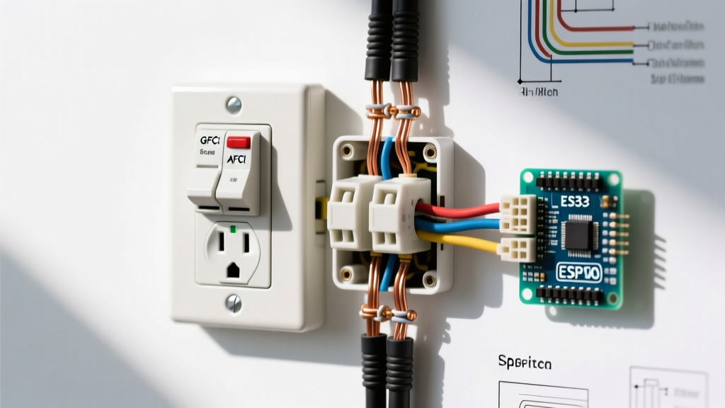
Ground Fault Circuit Interrupters (GFCIs) are critical life-saving devices mandated by the National Electrical Code (NEC) for areas where water and electricity intersect. For beginners, the most intimidating part of these devices is often the pair of buttons in the center of the receptacle. Understanding how the reset button on electrical outlet circuits functions is the first step toward successful installation and troubleshooting.
Unlike a standard breaker that protects wiring from overheating due to overcurrent, a GFCI protects humans from lethal shock. Inside the plastic housing, a differential current transformer continuously monitors the current flowing through the hot (line) and neutral wires. If it detects an imbalance as small as 4 to 6 milliamps—indicating that current is leaking to ground, potentially through a person—an internal silicon-controlled rectifier (SCR) triggers a solenoid. This solenoid physically snaps the internal contacts open, cutting power and causing the reset button to pop out.
Safety Warning: Before beginning any electrical work, always turn off the circuit breaker at the main panel and verify the absence of voltage using a non-contact voltage tester. Never assume a circuit is dead based solely on the position of a wall switch or the state of a GFCI reset button.
Tools and Materials for a 2026 GFCI Installation
To ensure a safe, code-compliant installation that prevents premature failure of the reset mechanism, you must use the correct tools. Modern electrical codes strictly enforce termination torque specifications to prevent loose connections that can cause arcing or phantom tripping.
- GFCI Receptacle: Leviton T5999-0W SmartlockPro (15A, approx. $18-$22) or Eaton GFTR15W. These feature 'Smartlock' technology that prevents the reset button from engaging if wired incorrectly.
- Wire Strippers: Klein Tools 11055 (10-18 AWG) for precise insulation removal without nicking the copper conductor.
- Voltage Tester: Fluke 2AC VoltAlert or similar CAT IV rated tester.
- Torque Screwdriver: Wiha 320P or Klein Tools 72100, calibrated to the manufacturer's specified torque (usually 14 in-lbs for 14/12 AWG wire).
- Electrical Tape: 3/4-inch wide Super 33+ vinyl tape for wrapping the device terminals.
Step-by-Step Beginner Wiring Tutorial
The most common reason a beginner fails to get the reset button on electrical outlet circuits to stay depressed is a 'Line/Load reversal'. The GFCI must receive incoming power on the correct terminals to function.
Step 1: Identify Line vs. Load
In a standard electrical box, you may find multiple cables. The 'Line' cable brings power from the breaker panel. The 'Load' cable carries power downstream to other outlets.
The Identification Trick: Cap all bare wires and wire nuts safely. Turn the breaker back on temporarily. Use your non-contact voltage tester to identify which black wire is hot. Turn the breaker back off. Mark the hot black wire and its corresponding white neutral wire with black electrical tape. This is your LINE pair.
Step 2: Prepare the Conductors
Strip exactly 3/4 of an inch of insulation from the black, white, and bare copper wires. Do not strip more, as exposed copper outside the terminal can cause a short. Do not strip less, as insulation trapped under the terminal screw will cause a high-resistance connection and eventual failure. Use the built-in strip gauge on the back of the Leviton T5999 to verify your length.
Step 3: Terminate the Line Wires
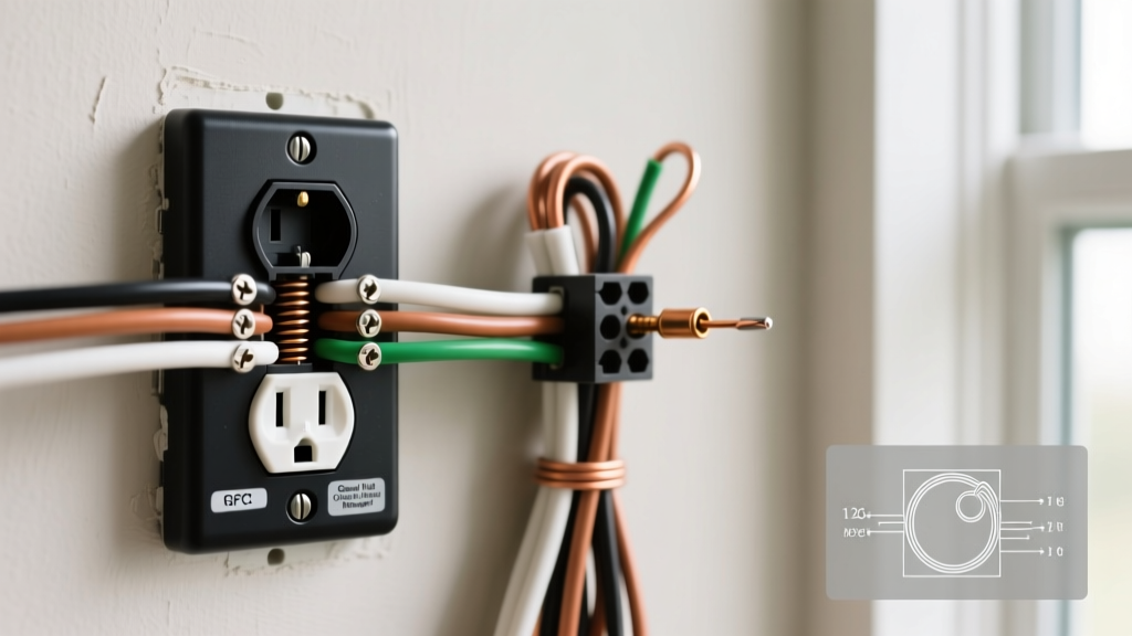
Connect the identified LINE black wire to the brass 'LINE' screw and the LINE white wire to the silver 'LINE' screw. Loop the wire clockwise around the screw so that tightening the screw pulls the loop closed. Use your torque screwdriver set to 14 in-lbs (or the specific value printed on the device's specification sheet) to secure the connection.
Step 4: Grounding and Load Connections
Attach the bare copper ground wire(s) to the green grounding screw. If you are protecting downstream outlets, connect the LOAD black and white wires to the brass and silver LOAD screws, respectively. If you are only protecting this single outlet, cap the load wires with wire nuts and do not connect them to the GFCI.
Step 5: Finalize and Test
Wrap the sides of the GFCI with two layers of electrical tape to cover the terminal screws, preventing accidental contact with the metal junction box. Push the wires neatly into the box, mount the device, and restore power. The reset button should now be ready to engage.
Downstream Protection vs. Single Location Wiring
Understanding when to use the LOAD terminals is crucial for circuit design. According to Leviton Residential GFCI Solutions, feeding downstream outlets through the LOAD terminals extends ground-fault protection to standard receptacles further down the circuit. However, this can complicate troubleshooting. If a downstream device develops a ground fault, the primary GFCI will trip, and the reset button on electrical outlet units upstream will pop out, leaving a beginner confused as to why the GFCI tripped when nothing was plugged into it. For beginners, 'pigtailing' all wires and only using the LINE terminals (providing single-location protection) is often the most reliable and easily troubleshooted method.
Troubleshooting: Why Won't the Reset Button Stay In?
If you have restored power and the reset button on electrical outlet circuits refuses to stay depressed, or if it trips immediately upon resetting, consult the diagnostic matrix below. Modern GFCIs feature internal lockout mechanisms that deliberately disable the reset button if the device is compromised or miswired.
| Symptom | Probable Cause | Diagnostic Step & Solution |
|---|---|---|
| Reset button will not push in at all | No power to LINE terminals or internal lockout triggered. | Verify 120V at LINE terminals with a multimeter. Check for tripped upstream breaker. |
| Button pushes in but immediately pops out | Line/Load reversal or active ground fault. | Swap Line and Load wires. Check downstream devices for water intrusion or faulty appliances. |
| Button stays in, but outlet has no power | Internal solenoid failure or open neutral. | Press the 'TEST' button. If it doesn't click and pop the reset button out, the GFCI is dead and must be replaced. |
| Trips randomly with no load attached | Phantom tripping from long wire runs or shared neutral. | Ensure the neutral on the load side is not shared with a non-GFCI circuit. Check for induced voltage on long runs. |
The 'Shared Neutral' Edge Case
A frequent beginner mistake in older homes or multi-wire branch circuits (MWBC) is sharing a single neutral wire between two different hot phases. A GFCI measures the differential between its specific hot and neutral. If the neutral current returns via a different path or splits to another circuit, the GFCI will read this as a ground fault and trip instantly. If your reset button on electrical outlet circuits trips the moment you plug in a lamp, verify that the neutral wire connected to the GFCI is dedicated solely to the hot wire on the same circuit.
Code Requirements and Monthly Maintenance
The U.S. Consumer Product Safety Commission (CPSC) strongly recommends testing all GFCI receptacles monthly to ensure the internal mechanical and electronic components have not degraded. Environmental factors, such as high humidity in bathrooms or UV exposure in outdoor patio boxes, can cause the internal SCR or solenoid to seize over time.
How to properly test the device:
- Plug a simple nightlight or voltage tester into the GFCI receptacle.
- Press the 'TEST' button. You should hear a distinct mechanical 'snap' and the reset button should pop out.
- Verify that the plugged-in light has turned off.
- Press the 'RESET' button firmly until it clicks and sits flush with the housing.
- Verify the light turns back on.
If the light does not turn off during the test phase, or if the reset button fails to re-engage, the device has failed its internal self-test and must be replaced immediately. As of 2026, all UL-listed GFCIs feature end-of-life (EOL) indicators; if the device flashes a red LED or physically locks out the reset button, it has reached the end of its operational lifespan and cannot be repaired.
Final Thoughts for the DIY Electrician
Mastering the installation of a GFCI receptacle bridges the gap between basic component swapping and true circuit comprehension. By respecting torque specifications, meticulously identifying line and load conductors, and understanding the physics behind the reset button on electrical outlet mechanisms, you ensure not only a functional circuit but a safe environment for your household. Always prioritize manufacturer instructions and local code amendments over general internet advice, and never hesitate to consult a licensed electrician if your junction box wiring presents an unrecognizable configuration.