
Translating Wiring Diagrams to Physical Enclosures
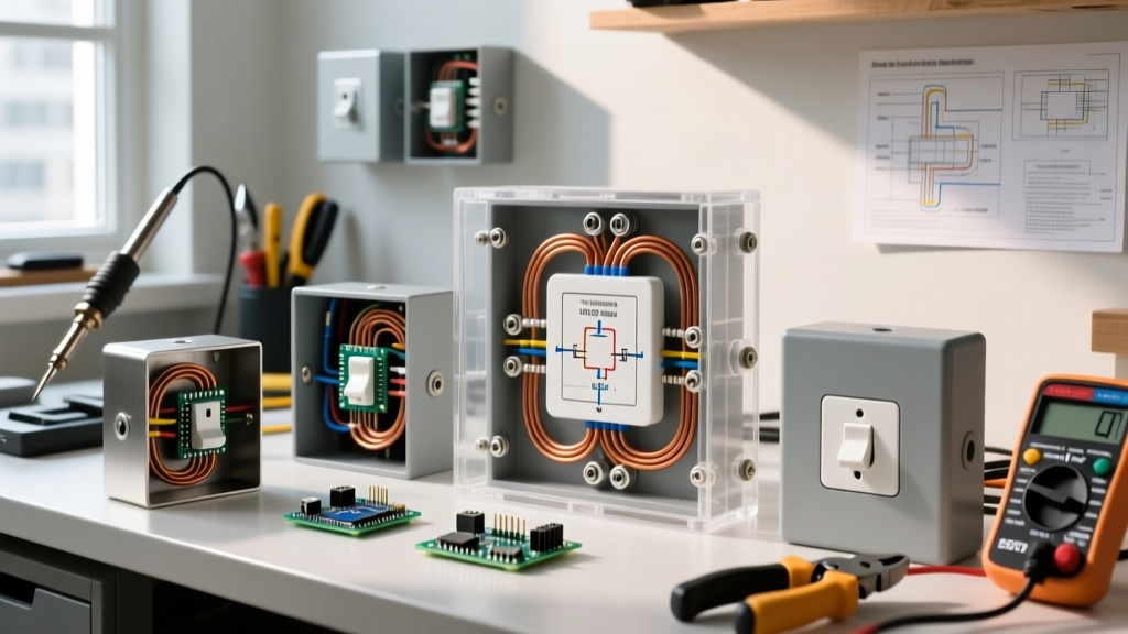
When reviewing an electrical schematic or wiring diagram, the enclosure is often represented merely as a dashed boundary or a simple rectangle. However, translating that 2D diagram into a physical installation requires selecting the correct electrical box for outlet terminations. The enclosure dictates wire bending space, heat dissipation, and structural mounting. In 2026, with the proliferation of smart receptacles and GFCI/AFCI combo devices that feature significantly deeper chassis depths, standard shallow boxes are increasingly obsolete. This guide bridges the gap between theoretical wiring diagrams and physical box selection, utilizing National Electrical Code (NEC) standards to ensure safe, compliant installations.
NEC Article 314: The Mathematics of Box Fill
Every wiring diagram that routes multiple cables into a single node must account for box fill capacity. According to the National Fire Protection Association (NFPA 70), NEC Article 314.16 mandates minimum volume allowances to prevent conductor insulation damage and overheating. When your diagram shows a daisy-chained receptacle (line and load), the physical box must accommodate the doubled conductor count.
Volume Allowance Table by Conductor Size
| Conductor Size (AWG) | Volume Allowance per Conductor (Cubic Inches) |
|---|---|
| 14 AWG | 2.00 cu in |
| 12 AWG | 2.25 cu in |
| 10 AWG | 2.50 cu in |
| 8 AWG | 3.00 cu in |
Practical Calculation: 20-Amp Receptacle on 12/2 NM-B
Assume your wiring diagram specifies a 20-amp commercial duplex receptacle fed by one 12/2 NM-B cable and feeding another (daisy-chain). Here is the exact fill calculation:
- Hot Conductors: 2 (12 AWG) = 2 allowances
- Neutral Conductors: 2 (12 AWG) = 2 allowances
- Equipment Grounding Conductor (EGC): 1 allowance for all grounds combined (12 AWG) = 1 allowance
- Internal Cable Clamps: 0 (assuming plastic box with no internal clamps) = 0 allowances
- Device Yoke (Receptacle): 2 allowances based on largest wire connected (12 AWG) = 2 allowances
Total Allowances: 7. Multiply by the 12 AWG volume factor (2.25 cu in).
Minimum Required Volume: 7 × 2.25 = 15.75 cubic inches.
A standard single-gang nail-on plastic box typically offers 18 to 22 cubic inches of volume, safely accommodating this diagram. However, if you add a second 12/2 cable (e.g., a split-wired receptacle), the required volume jumps to 20.25 cubic inches, necessitating a deep or extra-wide enclosure.
Material Selection Matrix: Metal vs. Non-Metallic
Wiring diagrams rarely specify box material unless dealing with specific grounding topologies or fire-rated assemblies. The choice between metallic and non-metallic (PVC) enclosures impacts both cost and installation methodology.
| Feature | Non-Metallic (PVC) - e.g., Carlon B618R | Metallic (Galvanized Steel) - e.g., Steel City 490 |
|---|---|---|
| Average Cost (2026) | $1.25 - $1.85 | $4.50 - $6.20 |
| Grounding Requirement | Device grounds via EGC wire only | Box must be bonded to EGC; metal yoke bonds to box |
| Fire Rating | Requires fire putty pads in rated walls | Inherently maintains 1-hour/2-hour fire ratings |
| Cable Entry | Integral nail-on clamps or ROMEX connectors | Requires separate 3/8" NM connectors (e.g., Halex) |
| Best Use Case | Residential wood-framed new construction | Commercial, exposed masonry, or fire-rated drywall |
Knockout (KO) Management and Diagrammatic Entry Points
In professional schematics, cable entry points are denoted by knockout (KO) indicators. A standard single-gang steel box features multiple 1/2" and 3/4" trade-size knockouts on the top, bottom, back, and sides. When executing the wiring diagram, you must only punch the KOs actively used for cable entry. Leaving unused KOs open violates OSHA Wiring Methods and Components Standards, as it exposes the enclosure interior to dust, debris, and accidental contact.
For metallic boxes, every NM-B cable entering a knockout requires a listed cable connector. The connector serves two purposes: it secures the cable against pull forces and protects the wire insulation from the sharp, stamped edges of the steel knockout. For non-metallic boxes with integral clamps, ensure the cable sheath extends into the box at least 1/4 inch past the clamp to satisfy NEC 314.17(C).
Retrofitting: Old Work Box Considerations
When a wiring diagram is applied to an existing finished wall (retrofitting), new-work nail-on boxes are useless. You must utilize old work or remodel boxes equipped with flip-clamps or Madison-style hangers. The Arlington FA100 (14 cu in) or the Madison Electric FA100 are industry standards for this scenario. These boxes feature integrated wing-flaps that pull flush against the back of the 1/2" drywall when the mounting screws are tightened. Note that remodel boxes typically have lower cubic inch capacities due to the space consumed by the mounting mechanisms, so strict adherence to the box fill math outlined above is critical.
Grounding Protocols for Metallic Enclosures
One of the most common errors when translating a wiring diagram to a metal electrical box for outlet installation is failing to bond the box itself to the equipment grounding conductor (EGC). According to NEC 250.148, a metal box must be grounded. If you are using a metal yoke receptacle in a metal box, the grounding path can be established through the mounting screws, provided the box is flush and the screw threads are not compromised by paint or drywall mud. However, best practice and a requirement in many commercial specs is to use a 10-32 green grounding screw to attach a 12 AWG copper pigtail directly to the threaded grounding hole in the back of the steel box. This pigtail is then wire-nutted to the incoming bare copper EGC and the receptacle's green grounding screw.
Smart Receptacles and Deep Box Requirements
Modern wiring diagrams increasingly feature smart outlets (e.g., Leviton Decora Smart Wi-Fi or Lutron Caseta). These devices contain internal relays, Wi-Fi radios, and heat sinks, resulting in chassis depths of 1.5 to 1.8 inches. A standard 18 cu in box leaves virtually no room for the required 6-inch wire leads and wire nuts. When your diagram specifies a smart receptacle, upgrade to a 22.5 cu in or 24 cu in deep single-gang box (such as the Carlon A222R-24) to maintain proper wire bending radius and prevent crushing the low-voltage antenna wires against the back of the enclosure.
Wire Bending Space Requirements (NEC 312.6)
Beyond cubic inch volume, wiring diagrams that route larger gauge wires (such as 10 AWG for 30-amp RV outlets or 8 AWG for heavy-duty equipment) must account for wire bending space. NEC Table 312.6(A) specifies the minimum distance from the cable entry knockout to the opposite wall of the enclosure. For 10 AWG wire, you need at least 2.0 inches of unobstructed bending space. For 8 AWG, this increases to 2.5 inches. Standard single-gang boxes are typically 2.0 inches deep, which is marginal for 10 AWG and entirely insufficient for 8 AWG. In these scenarios, your diagram must call for a 4-inch square steel box (e.g., Steel City 52171) with a single-gang plaster ring, providing 4.75 inches of depth and ample bending room.
Summary Checklist for Diagram Execution
- Verify Conductor Count: Count all hots, neutrals, and devices on the diagram to calculate minimum cubic inches.
- Select Material: Choose PVC for standard residential framing; choose steel for commercial, fire-rated, or exposed applications.
- Check Device Depth: Upgrade to deep boxes (22+ cu in) for GFCI, AFCI, or smart receptacles.
- Manage Knockouts: Use listed connectors for all entries; seal unused KOs with steel plugs.
- Bond Metal Boxes: Always use a 10-32 grounding screw and pigtail for metallic enclosures.
For further guidance on residential electrical safety and enclosure standards, consult the U.S. Consumer Product Safety Commission (CPSC) Electrical Safety Center. Properly matching your wiring diagram to the physical enclosure ensures a long-lasting, code-compliant, and safe electrical system.