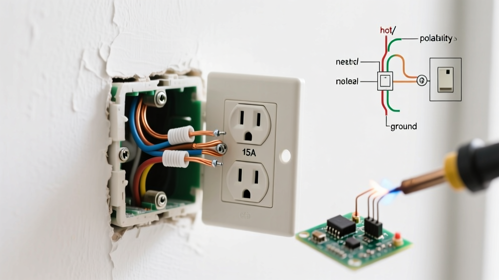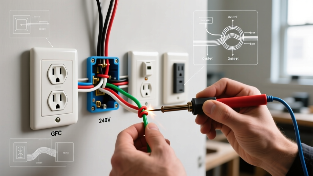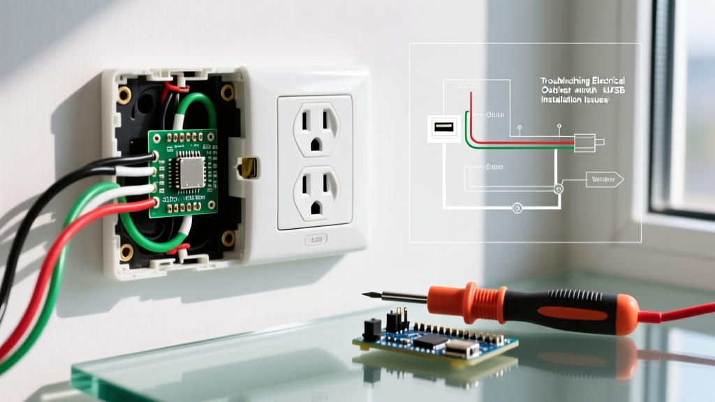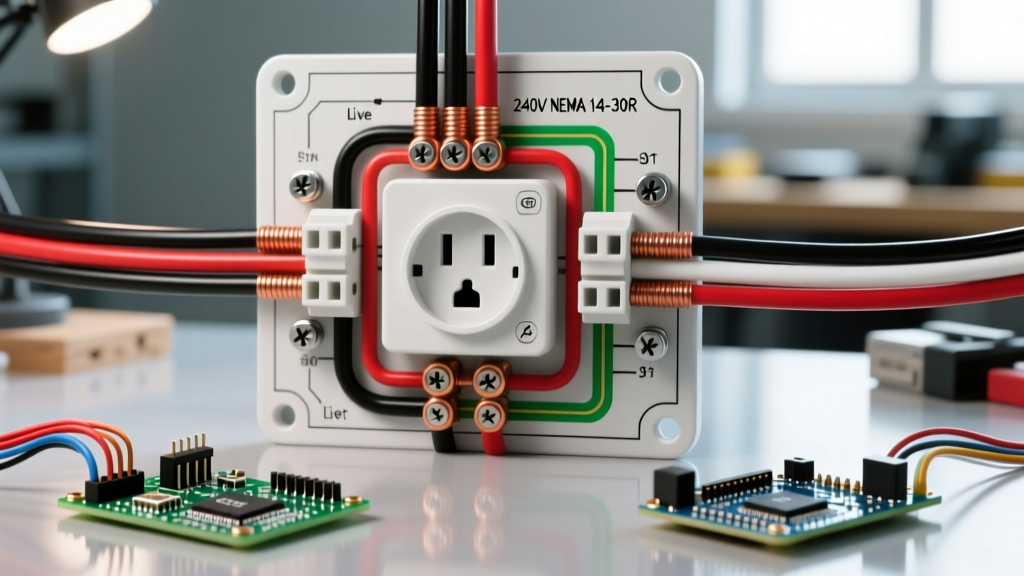

Understanding the Electrical Outlet GFCI: A Beginner's Guide
Upgrading or installing an electrical outlet GFCI (Ground Fault Circuit Interrupter) is one of the most critical safety improvements you can make in a modern home. Unlike standard receptacles, a GFCI continuously monitors the current flowing through the hot and neutral wires. If it detects an imbalance as small as 4 to 6 milliamps—indicating that current is leaking to ground, potentially through a person's body—it trips the circuit in roughly 25 milliseconds. According to the U.S. Consumer Product Safety Commission (CPSC), GFCIs have prevented thousands of electrocutions and significantly reduced residential electrical fires since their widespread adoption.
This comprehensive tutorial will walk you through the exact process of wiring an electrical outlet GFCI, adhering to the latest NFPA 70 National Electrical Code (NEC) standards. We will cover tool selection, the crucial difference between line and load terminals, and precise torque specifications that most DIY guides ignore.
⚠️ CRITICAL SAFETY WARNING: Never work on live electrical circuits. Always turn off the power at the main breaker panel and verify the absence of voltage using a non-contact voltage tester before touching any wires. If you are unsure about your home's wiring, hire a licensed electrician.
Where Are GFCI Outlets Required by Code?
Before beginning your installation, it is vital to understand where the NEC mandates GFCI protection. As of the latest code cycles, GFCI protection is required in areas where water and electricity are in close proximity. This includes:
- Kitchens: All 125-volt, 15- and 20-ampere receptacles serving countertop surfaces.
- Bathrooms: All receptacles within the bathroom space.
- Garages & Accessory Buildings: All 125V/250V receptacles up to 50 amps.
- Outdoors: All outdoor receptacles, including those on decks and patios.
- Crawlspaces & Basements: Unfinished areas at or below grade level.
- Laundry & Utility Sinks: Within 6 feet of the outside edge of the sink.
Essential Tools and Materials for 2026
To ensure a safe, code-compliant installation, you need the right equipment. Do not rely on cheap, uncalibrated testers or improper wire strippers.
- GFCI Receptacle: Leviton SmartlockPro 05325-WMP (20-Amp, 125V). Priced around $18-$22, this model features a lighted reset indicator and self-testing capabilities, which are highly recommended for modern installations.
- Non-Contact Voltage Tester (NCVT): Klein Tools NCVT-3 (~$35). This dual-range tester detects both standard and low voltage, ensuring your circuit is truly dead.
- Wire Strippers: Klein Tools 11055 (~$30) for clean, precise stripping without nicking the copper conductor.
- Torque Screwdriver: Wiha 01112 or similar, calibrated to inch-pounds. NEC 110.14(D) requires specific torque values for terminal connections to prevent arcing and fires.
- Wire Nuts & Pigtails: Ideal Wing-Nut connectors (Tan or Red) and 12 AWG THHN pigtails if your box has multiple neutrals.
The Golden Rule: Line vs. Load Terminals
The most common mistake beginners make when wiring an electrical outlet GFCI is confusing the LINE and LOAD terminals. The back of the receptacle is clearly labeled, but understanding their distinct roles is crucial.
| Terminal Type | Function | Wiring Scenario |
|---|---|---|
| LINE | Receives incoming power directly from the breaker panel. | Always used. The hot (black) and neutral (white) source wires connect here. |
| LOAD | Sends GFCI-protected power downstream to other standard outlets. | Only used if you intend to protect additional outlets on the same circuit. Leave empty if protecting a single location. |
Pro Tip: If you only need to protect the single electrical outlet GFCI and not downstream devices, connect your incoming power to the LINE terminals and leave the LOAD terminals completely empty. Cover the LOAD terminals with the included yellow warning tape to prevent future confusion.
Step-by-Step Installation Procedure
Step 1: Kill the Power and Verify
Locate the correct breaker in your main panel and switch it to the OFF position. Use your Klein NCVT-3 to test the existing outlet. Insert the tip into both the top and bottom slots. The tester must remain completely dark and silent. For added safety, use a multimeter set to AC voltage to confirm 0V between the hot and neutral slots.
Step 2: Identify Line and Load Wires
Remove the existing receptacle. If you see only one black and one white wire (plus a bare ground), you have a simple line-only setup. If you see two black and two white wires, you must identify which pair is the incoming power (Line). Method: Cap all bare wire ends, turn the breaker back on temporarily, and carefully use your NCVT to find the hot wire. The pair containing the hot wire is your LINE. Turn the breaker back off before proceeding.
Step 3: Strip Wires to Exact Specifications
Look at the back of your Leviton GFCI. You will see a 'STRIP GAUGE' molded into the plastic. For 12 AWG solid copper wire, the strip length is typically 5/8 inch. For 14 AWG, it is slightly shorter. Stripping too much leaves exposed copper outside the terminal (a shock hazard); stripping too little results in the screw clamping onto the wire insulation, causing a high-resistance connection that will melt under load.
Step 4: Connect the Ground Wire
Attach the bare copper or green ground wire to the green grounding screw at the bottom of the GFCI. If your metal electrical box also requires grounding, use a grounding clip or a pigtail to ensure both the box and the receptacle are bonded to ground.
Step 5: Terminate Line Conductors with Proper Torque
Connect the incoming black (hot) wire to the brass LINE terminal and the incoming white (neutral) wire to the silver LINE terminal. Crucial E-E-A-T Detail: Do not simply tighten the screws 'until they feel tight.' NEC 110.14(D) mandates that terminals be tightened to the manufacturer's specified torque. For the Leviton 05325-WMP, this is 14 in-lbs. Use a calibrated torque screwdriver. Under-torquing causes arcing; over-torquing can strip the screw or shear the wire.
Step 6: Mount, Restore Power, and Test
Carefully fold the wires into the back of the electrical box, ensuring no ground wires are touching the terminal screws. Secure the GFCI with the provided mounting screws. Turn the breaker back on. The green LED on the Leviton SmartlockPro should illuminate, indicating power is present and the device is properly reset. Press the 'TEST' button—the LED should turn off and the 'RESET' button should pop out. Press 'RESET' to restore power.
Troubleshooting Common GFCI Failures
Even with careful installation, issues can arise. Use this diagnostic matrix to resolve common edge cases:
| Symptom | Probable Cause | Solution |
|---|---|---|
| GFCI will not reset; button won't stay depressed. | Line and Load wires are reversed, or no power is reaching the LINE terminals. | Verify incoming power is on LINE terminals. Check breaker. |
| TEST button does not trip the receptacle. | Open ground, or internal GFCI mechanism failure. | Check ground wire continuity. Replace GFCI if ground is verified. |
| GFCI trips randomly under heavy load. | Loose neutral connection causing current imbalance, or shared neutral on multi-wire branch circuit. | Re-torque neutral terminal to 14 in-lbs. Ensure neutrals are not shared with another circuit. |
Frequently Asked Questions
Can I install a GFCI outlet without a ground wire?
Yes. The NEC allows you to replace an ungrounded (2-prong) receptacle with a GFCI. The GFCI provides shock protection by monitoring current imbalance, which does not require a ground wire to function. However, you must label the outlet with the included 'GFCI Protected' and 'No Equipment Ground' stickers. Note that this does not provide a true equipment ground for sensitive electronics like surge protectors.
Should I use the back-wire holes or the side terminal screws?
For 12 AWG wire, always use the side terminal screws or the screw-to-clamp back-wiring mechanism if your model supports it. Avoid 'push-in' back-stab connections on standard receptacles, as they rely on small spring tabs that can loosen over time due to thermal expansion and contraction, leading to high resistance and potential fire hazards.
What is the difference between GFCI and AFCI?
A GFCI (Ground Fault Circuit Interrupter) protects people from electrical shock by detecting current leaking to ground. An AFCI (Arc Fault Circuit Interrupter) protects the building from fires by detecting dangerous electrical arcing. Modern electrical panels often use Dual Function (DF) breakers that provide both, but the physical electrical outlet GFCI receptacle remains the primary defense against shock in wet locations.