
Understanding Electrical Outlet Repair vs. Replacement
When homeowners search for information on how to repair electrical outlet components, they often misunderstand the scope of the work. Under the National Electrical Code (NEC), you rarely 'repair' the physical plastic or metal housing of a receptacle. Instead, repairing an outlet means restoring the integrity of the wiring connections, upgrading outdated terminations, and ensuring the circuit meets current safety standards. According to the National Fire Protection Association (NFPA), electrical distribution and lighting equipment are consistently among the leading causes of home structure fires, often stemming from loose connections and degraded terminations.
Before picking up a screwdriver, you must determine whether your specific issue requires a connection repair or a full device replacement to maintain code compliance.
| Component Issue | Action Required | NEC Code Reference |
|---|---|---|
| Push-in 'backstabbed' wire connections | Repair: Remove and terminate on side screws or pigtail | 110.14(D) (Terminations) |
| Cracked faceplate or broken mounting yoke | Replace: Entire receptacle and faceplate | 406.4(A) (Faceplates) |
| Missing ground fault protection in wet areas | Replace: Install GFCI receptacle | 210.8(A) (GFCI Protection) |
| Loose terminal screw causing arcing | Repair: Re-terminate and torque to manufacturer spec | 110.14(D) (Torque Requirements) |
| Non-Tamper-Resistant (TR) slots in dwelling | Replace: Upgrade to TR receptacle | 406.12 (Tamper-Resistant) |
Essential Tools for Code-Compliant Outlet Repair
To properly repair an electrical outlet to 2026 safety standards, you need more than a standard flathead screwdriver. Modern code compliance requires precision and verification. Budget approximately $150 to $200 for a professional-grade DIY toolkit.
- Voltage Verification: Klein Tools NCVT-3 Non-Contact Voltage Tester ($35) and a standard 3-prong receptacle tester ($15).
- Insulated Hand Tools: Wiha 1000V Insulated Screwdriver Set ($45) to protect against accidental contact with live bus bars in crowded panels.
- Wire Preparation: Klein Tools 11055 Wire Stripper ($30) to ensure precise jacket removal without nicking the copper conductor.
- Torque Measurement: CDI Torque Screwdriver (10-50 in-lbs range) ($120). This is critical for NEC 110.14(D) compliance.
- Connectors: WAGO 221 Lever-Nuts (assorted kit, $25) or IDEAL 33 Orange Wire-Nuts for secure pigtailing.
Step-by-Step: How to Repair Electrical Outlet Terminations
The most common reason an outlet fails or causes a fire is a high-resistance connection. Follow this procedure to repair the wiring terminations safely.
Step 1: Lockout/Tagout (LOTO) and Verification
Never rely solely on a wall switch to de-energize a circuit. Locate the correct breaker in your main panel and turn it off. Following OSHA's hazardous energy control guidelines, place a physical lock or heavy tape over the breaker to prevent accidental re-engagement. Test the outlet with your NCVT-3 and a multimeter (probing from hot to ground, and hot to neutral) to confirm 0V.
Step 2: Inspect Junction Box Fill
Before adding pigtails to repair a damaged wire, verify your box has the physical volume to accommodate them. Per NEC 314.16, a standard 14 AWG wire counts as 2.0 cubic inches, and a 12 AWG wire counts as 2.25 cubic inches. The receptacle itself counts as two wire volumes. If you are working in a standard 18-cubic-inch single-gang nail-on box with 12 AWG wire, you are already at maximum capacity with just two cables and a receptacle. If your repair requires adding wire nuts and pigtails, you may need to install an old-work deep box (22+ cubic inches) to remain code-compliant.
Step 3: Remove Backstabbed Connections
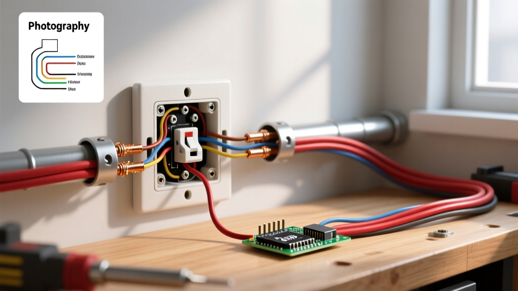
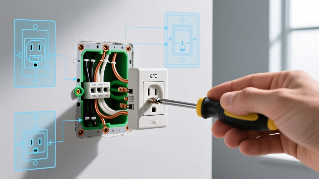
Push-in (backstab) terminals rely on a small internal spring-metal tang gripping the wire. Over years of thermal cycling (heating under load, cooling when off), these tangs lose tension, leading to arcing. Do not reuse backstabbed connections. Use a small flathead screwdriver to press the release slot and pull the wires out. If the wire is deeply scored or pitted from previous arcing, cut it back and strip a fresh 3/4-inch of insulation.
Step 4: Form the J-Hook and Terminate
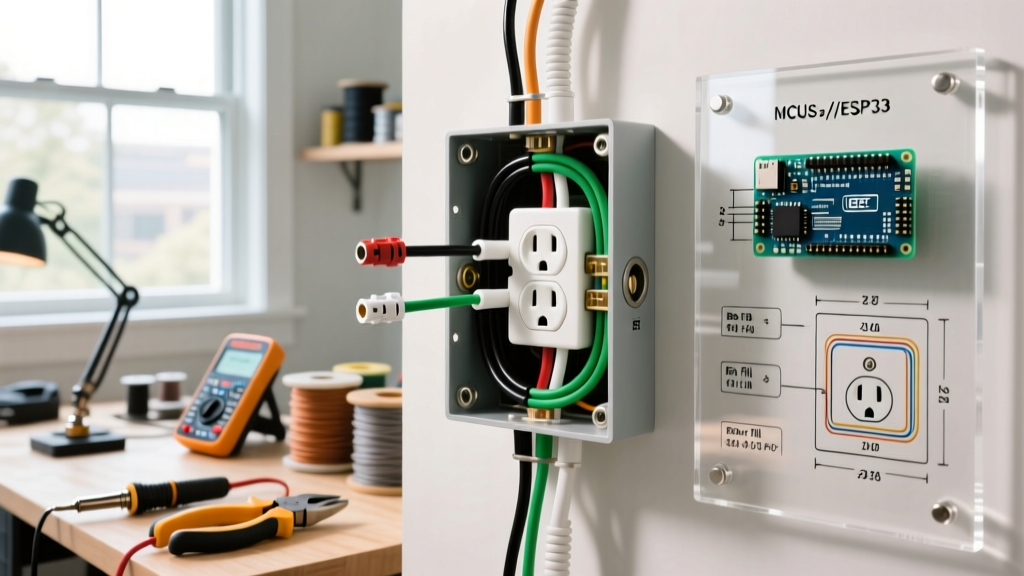
When moving wires to the side-screw terminals, use your wire strippers to bend the exposed copper into a tight 'J-hook'. Loop the hook clockwise around the terminal screw. This ensures that tightening the screw pulls the loop closed rather than pushing it out. The insulation jacket should sit flush against the metal yoke—no bare copper should be visible outside the terminal, which prevents accidental shorting to the grounded metal box.
Step 5: Apply Manufacturer Torque Specifications
This is the most overlooked step in DIY electrical repair. NEC 110.14(D) mandates that terminations must be torqued to the manufacturer's specifications. For a standard Leviton 5362 or Eaton TRCR15 duplex receptacle, the required torque is typically 14 in-lbs for 14 AWG wire and 16 in-lbs for 12 AWG wire. Use your torque screwdriver to tighten the terminal screws until the tool clicks. This prevents both under-tightening (which causes arcing) and over-tightening (which strips the brass threads or crushes the copper).
Safety Warning: Never repair a melted or discolored receptacle housing. Discoloration indicates severe thermal damage that has compromised the structural integrity of the thermoplastic. Replace the entire device immediately and investigate the circuit for continuous overloading.
Critical Code Violations to Avoid During Repair
When learning how to repair electrical outlet wiring, avoid these dangerous and illegal shortcuts that frequently appear in older homes.
The 'Bootleg' Ground
If you open an outlet and find a jumper wire connecting the neutral (silver) terminal to the ground (green) terminal, you have found a bootleg ground. This was historically done to trick 3-prong receptacle testers into reading 'correct' on ungrounded circuits. This is a lethal shock hazard. If the neutral wire disconnects anywhere upstream, the metal chassis of any plugged-in appliance will become energized with 120V. Remove the jumper immediately. If no equipment grounding conductor exists in the box, NEC 406.4(D) requires you to replace the receptacle with a GFCI device and label it 'No Equipment Ground'.
Reverse Polarity
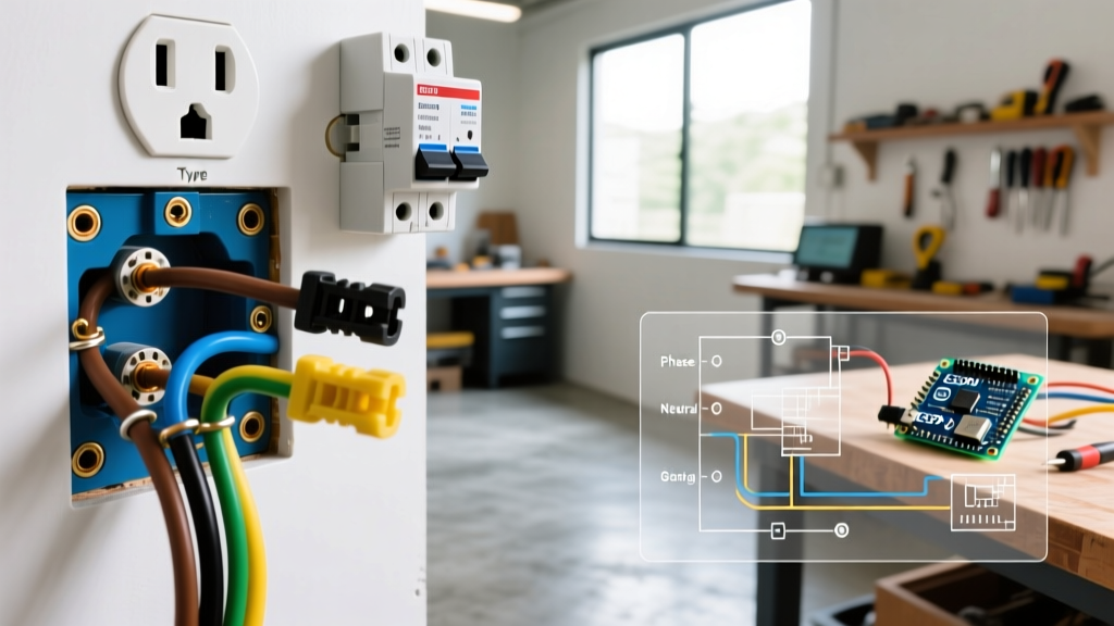
Always ensure the black (hot) wire is connected to the brass-colored screw, and the white (neutral) wire is connected to the silver-colored screw. Reverse polarity leaves the internal components of plugged-in devices energized even when the device's internal switch is turned off, posing a severe shock risk during maintenance or bulb changes.
Special Considerations: Aluminum Wiring and GFCI/AFCI
If your home was built between 1965 and 1973, you may encounter solid aluminum branch wiring. Aluminum expands and contracts at a different rate than copper, causing standard brass terminal screws to loosen over time, leading to fires. You cannot simply repair an aluminum-wired outlet by tightening the screws on a standard copper-rated receptacle.
According to the U.S. Consumer Product Safety Commission (CPSC), aluminum wiring requires specialized mitigation. To repair an outlet on an aluminum circuit, you must either:
- Use a receptacle specifically rated CO/ALR (Copper/Aluminum Revised).
- Pigtail the aluminum wire to a short copper lead using an ILSCO Alumiconn lug connector or an IDEAL Twister Al/Cu wire nut (purple), then connect the copper pigtail to a standard receptacle.
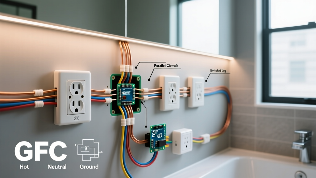
Finally, if you are repairing an outlet in a kitchen, bathroom, garage, or outdoor location, NEC 210.8 mandates GFCI protection. Furthermore, modern 2026 code adoptions increasingly require combination AFCI/GFCI protection in living areas. If a standard receptacle keeps tripping, do not attempt to bypass the internal trip mechanism. The repair requires diagnosing the downstream circuit for neutral-to-ground faults or replacing the aging GFCI sensor module entirely.
Final Verification
Once the physical repair and torquing are complete, carefully fold the wires into the box. Push the ground wires to the back, followed by the neutrals, and finally the hots, ensuring no wires are pinched against the sharp edges of the metal junction box. Secure the receptacle yoke to the box using the provided 6-32 machine screws. Restore power at the breaker and use a 3-prong receptacle tester to confirm correct wiring and proper GFCI trip functionality before considering the job complete.