
The Anatomy of a Dead Receptacle: An Inspection & Testing Guide
When you plug in a device and nothing happens, the immediate question is: why would an electrical outlet stop working? While it is tempting to assume the receptacle itself has failed, modern electrical engineering dictates that the outlet is rarely the root cause. More often, the failure lies in an upstream connection, a tripped protection device, or a degraded wire termination. According to the National Fire Protection Association (NFPA), electrical failures or malfunctions are a leading cause of home fires, making proper diagnostic testing a critical safety skill rather than just a convenience.
This inspection and testing guide will walk you through a systematic, professional-grade methodology to isolate the fault. We will move from non-invasive visual checks to advanced True-RMS multimeter diagnostics, equipping you with the exact data points needed to restore power safely.
Phase 1: The "No-Tool" Triage and Protection Reset
Before pulling out any testing equipment, you must rule out the most common and easily reversible protection trips. Modern residential circuits are heavily protected by ground-fault and arc-fault interrupters.
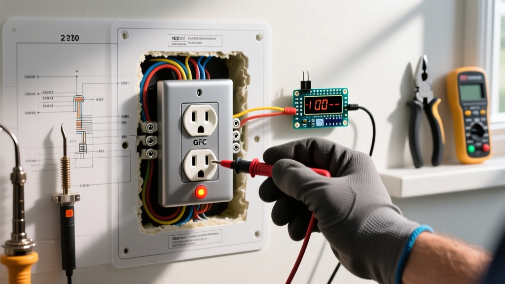
- GFCI Receptacle Trips: Check the outlet for "Test" and "Reset" buttons. If the reset button has popped out, press it firmly until it clicks. If it immediately pops back out, you have a downstream ground fault or a failed internal solenoid. Note that as of the 2026 NEC adoption cycle, GFCI protection is required in virtually all 125V, 15A, and 20A residential areas.
- AFCI Breaker Trips: Go to your main electrical panel. Look for AFCI (Arc-Fault Circuit Interrupter) breakers, such as the Eaton BR120AF or Siemens QAF2 series. These breakers feature an LED diagnostic light or a digital display. If the breaker has tripped due to an arc fault (often caused by a loose neutral or a damaged wire behind the drywall), it will refuse to reset until the fault is cleared.
- Standard Thermal/Magnetic Trips: If a standard breaker is tripped, the toggle will sit in the middle "neutral" position. Push it firmly to the OFF position, then snap it to ON. If it immediately snaps back with a loud pop, you have a dead short circuit. Do not attempt to force it on.
Phase 2: Non-Contact Voltage Testing (NCVT)
If the breakers are on and the GFCI is reset, the next step is to verify the presence of an electromagnetic field at the receptacle using a Non-Contact Voltage Tester. We recommend the Klein Tools NCVT-3TI (approximately $35 in 2026), which tests both standard voltage (12V to 1000V) and low voltage.
- Insert the tip of the NCVT into the smaller (hot) slot of the outlet.
- If the tool beeps and glows red, the hot conductor is energized up to the receptacle face.
- If there is no beep, the hot leg is open somewhere between the panel and this outlet.
Inspector's Note: An NCVT only detects the capacitive coupling of the hot wire's electromagnetic field. It cannot verify a complete circuit or the integrity of the neutral wire. A "hot" reading on an NCVT does not guarantee the outlet can deliver current under load.
Phase 3: True-RMS Multimeter Diagnostics
To truly understand why an electrical outlet stops working under load, you must measure voltage potential across different conductor pairs. You will need a True-RMS digital multimeter (DMM) like the Fluke 117 (retailing around $230) or the more budget-friendly Klein Tools MM400 ($50). True-RMS is essential for accurately reading circuits that may have harmonic distortion from modern LED drivers or smart home electronics.
Set your DMM to AC Voltage (V~) and perform these three critical tests:
Test A: Hot to Neutral (H-N)
Insert the red probe into the smaller (hot) slot and the black probe into the larger (neutral) slot. A healthy circuit should read between 115V and 125V. If you read 0V, you have an open hot or an open neutral.
Test B: Hot to Ground (H-G)
Insert the red probe into the hot slot and the black probe into the round grounding hole. This should also read 115V to 125V. This test confirms that the grounding path is intact and bonded back to the panel.
Test C: Neutral to Ground (N-G)
Insert the black probe into the neutral slot and the red probe into the ground hole. This reading should be under 2V (ideally less than 0.5V). A higher reading indicates voltage drop on the neutral wire, meaning the neutral connection is loose, degraded, or undersized for the load.
Decoding Your Multimeter Readings
Use this diagnostic matrix to pinpoint the exact failure mode based on your multimeter results:
| Hot-Neutral (H-N) | Hot-Ground (H-G) | Neutral-Ground (N-G) | Diagnosed Failure Mode |
|---|---|---|---|
| 120V | 120V | < 2V | Circuit is healthy. Device plugged in is likely faulty. |
| 0V | 120V | 0V | Open Neutral. The hot wire is intact, but the neutral return path is broken upstream. |
| 0V | 0V | 0V | Open Hot. The breaker is off, tripped, or the hot wire is severed/disconnected upstream. |
| 120V | 0V | 120V | Open Ground / Reversed Polarity. Dangerous condition; grounding path is missing or wires are swapped. |
| 40V - 90V | 120V | > 30V | High-Resistance Neutral. Loose backstabbed connection or corroded wire nut causing severe voltage drop. |
Phase 4: Physical Tear-Down and Thermal Inspection
If your multimeter indicates an open neutral, open hot, or high-resistance connection, it is time to open the receptacle. Turn off the circuit breaker and verify zero voltage with your NCVT before touching any wires.
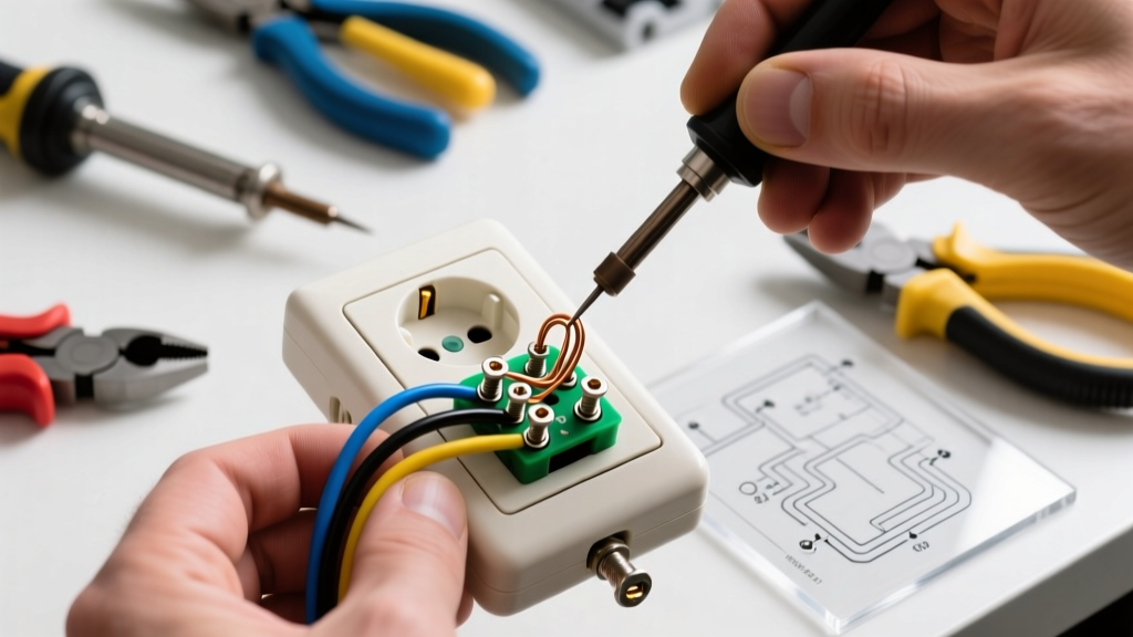
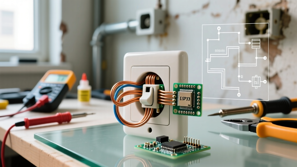
Unscrew the faceplate and extract the receptacle from the junction box. Inspect for the following specific failure modes:
The "Backstab" Push-In Failure
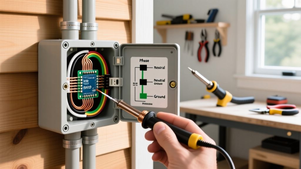
The most common reason an older electrical outlet stops working is the failure of push-in (backstabbed) wire terminations. Inside the receptacle, a small brass spring grips the 14 AWG or 12 AWG solid copper wire. Over 5 to 10 years, the thermal expansion and contraction cycles caused by drawing current (like running a space heater or vacuum) cause the spring tension to relax. This creates a micro-gap, leading to arcing, high resistance, and eventually a complete open circuit. Always cut off backstabbed wires, strip them back to fresh copper, and terminate them using the side screw terminals or a pigtailed wire nut.
Thermal Degradation and Melted PBT
Inspect the thermoplastic housing (typically Polybutylene Terephthalate, or PBT). If you see brown scorch marks, melted plastic around the terminal screws, or a distinct acrid odor, the outlet has experienced severe thermal runaway. This is often caused by an undersized wire (e.g., 14 AWG on a 20A breaker) or a loose screw terminal. The Consumer Product Safety Commission (CPSC) strongly advises replacing any receptacle showing signs of thermal damage immediately, as the internal contacts are permanently compromised.
Advanced Edge Cases: MWBCs and Phantom Voltage
Sometimes, the reason an outlet stops working defies basic logic. Two advanced scenarios frequently stump DIYers:
- Multi-Wire Branch Circuits (MWBC): In an MWBC, two hot wires (on different phases) share a single neutral wire. If an electrician previously worked on the panel and removed the handle-tie, or if a neutral wire nut in an upstream junction box vibrated loose, the shared neutral can float. This can cause 240V to be pushed across your 120V appliances, destroying them, while making the outlet appear "dead" or erratic. Always check for two hot wires entering the junction box on an MWBC.
- Phantom (Ghost) Voltage: If your high-impedance digital multimeter reads 40V to 90V on a dead circuit, but an NCVT shows no field, you are likely reading capacitive coupling from an adjacent live wire running in the same Romex cable or conduit. To confirm, use a low-impedance (LoZ) multimeter or plug in an incandescent test light. If the voltage drops to zero under the LoZ test, the circuit is truly dead (open hot), and the initial reading was just phantom voltage.
When to Call a Licensed Electrician
While replacing a standard 15A duplex receptacle (like the Leviton T5262) is a straightforward DIY task costing under $3 in parts, certain conditions require a licensed professional. According to OSHA electrical safety guidelines, working on live panels or dealing with degraded infrastructure poses severe arc-flash and electrocution risks. Call a pro if you encounter:
- Aluminum Wiring: Common in homes built between 1965 and 1973. Aluminum requires special CO/ALR rated receptacles and antioxidant paste (like Noalox) to prevent galvanic corrosion and fires.
- Missing Grounding Conductor: If your multimeter reads 0V from Hot to Ground, and you have two-prong ungrounded outlets, upgrading to a 3-prong outlet without running a new ground wire is a code violation (unless you install a GFCI and label it "No Equipment Ground").
- Burnt or Melted Panel Bus Bars: If the breaker feels spongy, won't stay seated, or shows scorch marks on the panel dead-front, the main bus bar may be damaged.
Summary
Answering the question of why an electrical outlet stops working requires moving past guesswork and relying on systematic electrical testing. By utilizing a non-contact voltage tester to trace the hot leg, and a True-RMS multimeter to measure voltage drop across the neutral and ground paths, you can accurately diagnose open circuits, loose terminations, and high-resistance faults. Always prioritize safety, terminate wires using screw terminals rather than push-in backstabs, and ensure your repairs align with the latest NEC standards to keep your home's electrical system safe and reliable.