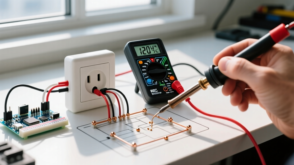

The Anatomy of a Dead Outlet: Where Power Fails
When you plug in a lamp, vacuum, or phone charger and get zero response, the immediate question is: why would electrical outlet stop working? According to the Electrical Safety Foundation International (ESFI), electrical failures and malfunctions account for over 51,000 home fires annually. A dead receptacle is rarely a mystery; it is almost always a localized failure in the circuit's continuity, a tripped protection device, or a degraded physical connection.
For DIY beginners, troubleshooting a dead outlet bridges the gap between basic home maintenance and introductory electrical installation. This tutorial will walk you through a systematic diagnostic process, explain the most common failure modes, and provide a step-by-step guide to safely replacing a faulty 15-amp duplex receptacle.
Phase 1: The 'No-Tools' Diagnostic Sequence
Before you grab a screwdriver and remove a faceplate, you must eliminate external variables. Roughly 60% of 'dead' outlets are actually victims of upstream interruptions.
1. The GFCI Daisy-Chain Effect
Ground Fault Circuit Interrupter (GFCI) outlets are required by the National Electrical Code (NEC) in wet areas like kitchens, bathrooms, and garages. A single GFCI receptacle often protects multiple standard downstream outlets via its 'LOAD' terminals. If a GFCI trips, every outlet wired to its load side will instantly stop working.
- The Fix: Locate the nearest GFCI outlet (often in a bathroom or garage) and press the 'RESET' button. If it clicks and stays in, check your dead outlet again.
2. The Switched 'Half-Hot' Receptacle
In living rooms and bedrooms, builders frequently wire duplex receptacles so the top half is controlled by a wall switch, while the bottom half remains always hot. This is done by breaking the brass fin tab on the hot side of the receptacle.
- The Fix: Flip every wall switch in the room. If the outlet comes to life, you have a switched receptacle, not a broken one.
3. Tripped AFCI/GFCI Breakers
Modern electrical panels utilize Arc Fault Circuit Interrupter (AFCI) and GFCI breakers. Unlike standard breakers that only trip on overcurrent (e.g., a 15A draw on a 15A circuit), AFCI breakers trip when they detect dangerous arcing signatures caused by loose wires or damaged cords.
- The Fix: Open your main panel. Look for a breaker with a 'TEST' button that is sitting in the middle (tripped) position. Turn it fully OFF, then firmly push it to the ON position.
Phase 2: Voltage Testing & Physical Inspection
If Phase 1 fails, you must verify the absence or presence of voltage. Never assume a circuit is dead just because a lamp won't turn on. Invest in a reliable non-contact voltage tester (NCVT), such as the Klein Tools NCVT-2 (approx. $28), which detects voltage from 12V to 1000V AC.
Safety Warning: The U.S. Consumer Product Safety Commission (CPSC) strongly advises using properly rated testing equipment before touching any internal wiring. Always test your NCVT on a known live circuit first to ensure the tool's battery is functional.
Removing the Receptacle
- Turn off the circuit breaker controlling the outlet.
- Test the outlet slots with your NCVT to confirm zero voltage.
- Remove the single center screw on the faceplate (usually a flathead or Phillips) and pull the plate away.
- Remove the two 6-32 mounting screws securing the receptacle to the electrical box.
- Gently pull the receptacle out, keeping the wires attached for visual inspection.
Common Failure Modes: Why Receptacles Die
Once the outlet is exposed, look for the physical culprits. The table below outlines the most frequent reasons an electrical outlet stops working under the hood.
| Failure Mode | Primary Symptom | Root Cause | Est. Repair Cost |
|---|---|---|---|
| Backstabbed Push-In Wires | Intermittent power; works when wiggled | Internal brass spring loses tension due to thermal expansion/contraction, breaking the connection. | $2.50 (New Receptacle) |
| Loose Neutral (White Wire) | Outlet dead; downstream outlets also dead | Wire nut connection in the back of the box vibrated loose or was poorly stripped. | $0 (Re-tighten) |
| Burnt/Melted Terminals | Brown discoloration; faint fishy/plastic smell | High resistance connection generated excessive heat, melting the thermoplastic housing. | $5 - $15 (Heavy Duty Receptacle) |
| Broken Brass Fin Tab | Half the outlet is dead | Previous installer broke the hot-side tab but forgot to wire a switch, or vice versa. | $2.50 (New Receptacle) |
Note: If you see melted plastic, scorched wires, or a 'fishy' odor, the National Fire Protection Association (NFPA) recommends replacing the damaged wires and the receptacle immediately, as this is a primary precursor to electrical fires.
Phase 3: Step-by-Step Outlet Replacement Tutorial
If your inspection reveals backstabbed wires, burnt terminals, or a cracked housing, it is time to install a new receptacle. For standard 15-amp residential circuits, we recommend a commercial-grade Tamper Resistant (TR) receptacle, such as the Leviton R52-05320-WMP (approx. $3.50). Commercial-grade units feature thicker internal brass contacts that resist the thermal fatigue that kills cheaper builder-grade units.
Step 1: Prepare the Wires
Cut off the old, damaged ends of the copper wire using your wire strippers. Strip exactly 5/8 inch of insulation off the black (hot), white (neutral), and bare/green (ground) wires.
- Pro Tip: Exposing more than 3/4 inch creates a shock hazard by leaving bare copper exposed outside the terminal. Exposing less than 1/2 inch results in the screw clamping onto the plastic insulation, causing high resistance and eventual arcing.
Step 2: Form the J-Hooks
Using needle-nose pliers, bend the stripped end of each wire into a tight 'J' shape or shepherd's hook. This ensures maximum surface area contact beneath the screw head.
Step 3: Make the Connections
Never use the push-in 'backstab' holes on the back of the new receptacle. Always use the side terminal screws.
- Ground (Green Screw): Attach the bare copper or green wire first. This establishes your safety path to ground.
- Neutral (Silver Screw): Attach the white wire. Loop it clockwise around the screw. Clockwise looping ensures that tightening the screw pulls the wire loop tighter rather than pushing it out.
- Hot (Brass Screw): Attach the black wire to the brass screw, again looping clockwise.
Step 4: Torque and Seat the Receptacle
Tighten the terminal screws firmly. While NEC Article 110.14(D) mandates specific torque values for larger terminations, standard 15A residential receptacles require the screws to be tightened to roughly 14 in-lbs. For a beginner using a standard #2 Phillips screwdriver, this means turning until the screw is completely snug and the wire cannot be pulled loose with a firm tug.
Step 5: Fold and Mount
Carefully fold the wires back into the electrical box. Push the ground wires to the very back, followed by the neutrals, and finally the hots. Seat the receptacle flush against the drywall or plaster, and secure it with the two 6-32 mounting screws. Finally, attach your new UL-listed faceplate.
Final Verification
Return to your electrical panel and turn the breaker back ON. Plug a simple lamp or a dedicated receptacle tester (like the Gardner Bender GRT-300, approx. $8) into the newly installed outlet. The tester's lights will confirm correct wiring, proper grounding, and correct polarity. By understanding why electrical outlets stop working and mastering this fundamental replacement technique, you have taken a massive step forward in your home electrical DIY journey.