
Understanding the Well Pump Pressure Switch
The pressure switch is the central nervous system of any residential or agricultural water system. It monitors the PSI inside your pressure tank and acts as the mechanical trigger to open or close the electrical circuit powering the pump motor. Finding a reliable pressure switch wiring diagram for well pump installations is critical, as improper wiring can lead to motor burnout, electrical fires, or catastrophic water hammer effects.
In 2026, while smart variable-frequency drive (VFD) constant pressure systems are gaining market share, traditional mechanical switches remain the backbone of over 75% of existing submersible and shallow well jet pump systems. This guide provides exact wiring schematics, terminal identifications, and National Electrical Code (NEC) compliance metrics for both 2-wire and 3-wire configurations.
Core Components: Square D Pumptrol and Alternatives
The industry standard for decades has been the Schneider Electric Square D Pumptrol series. The most ubiquitous model is the FSG2 (typically preset to 30/50 PSI), which retails between $22 and $28. For high-capacity agricultural pumps exceeding 2 HP, the FYG series is required to handle the increased amperage.
Expert Tip: If your well is prone to dropping water levels or running dry, upgrade to the FSG2J-M4 model. This variant includes a Low Pressure Cut-Off (LPCO) feature that mechanically trips the switch open if system pressure falls 10 PSI below the cut-in setting, preventing the pump from running without water and destroying the impellers.
2-Wire vs. 3-Wire Submersible Pump Configurations
Before consulting a wiring diagram, you must identify your pump's wire configuration. Submersible pumps generally fall into two categories:
- 2-Wire Pumps: Contain the start capacitor and relay internally within the waterproof motor housing. The pressure switch directly interrupts the main power legs.
- 3-Wire Pumps: Require an above-ground control box that houses the start capacitor, run capacitor, and relay. The pressure switch only interrupts the common (black) wire, while the control box manages the starting torque sequence.
240V Pressure Switch Wiring Diagram for Well Pump (2-Wire)
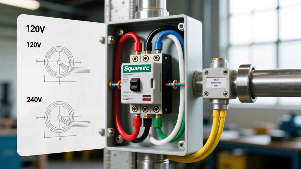
Most modern submersible pumps (1 HP to 3 HP) operate on 240V single-phase power. A 240V circuit utilizes two hot legs and a ground; no neutral wire is present at the switch.
Step-by-Step 240V Terminal Connections
- Power Off: Lock out the 2-pole breaker at the main panel. Verify zero voltage with a non-contact tester and a digital multimeter.
- Line Side (Power In): Connect the two hot wires (typically Black and Red, or Black and White re-identified with black tape) from the breaker panel to the bottom terminals of the switch, marked L1 and L2 (or 1 and 2).
- Load Side (Power Out): Connect the two hot wires leading down the well casing to the pump to the top terminals, marked T1 and T2 (or 3 and 4).
- Grounding: Splice the bare copper ground wires together using a wire nut, and attach a pigtail to the green grounding screw on the switch's metal mounting base. According to the National Electrical Code (NEC), all exposed non-current-carrying metal parts of pump equipment must be bonded to the equipment grounding conductor.
- Torque: Tighten terminal screws to 12-15 in-lbs. Loose connections cause high-resistance arcing, which melts the plastic housing.
120V Pressure Switch Wiring Diagram for Well Pump (Shallow Well)
Shallow well jet pumps (typically 1/2 HP to 3/4 HP) often operate on 120V. This circuit requires one hot wire, one neutral wire, and a ground.
- Line Side: Connect the 120V Hot (Black) from the single-pole breaker to L1. Connect the Neutral (White) to L2.
- Load Side: Connect the Pump Hot (Black) to T1. Connect the Pump Neutral (White) to T2.
- Ground: Bond all bare copper grounds to the green chassis screw.
3-Wire Submersible Pump Control Box Wiring Matrix
Wiring a 3-wire system is more complex because the pressure switch does not connect directly to the pump motor; it connects to the control box. As detailed in technical bulletins from major motor manufacturers like Franklin Electric, the control box requires four wires running downhole (Black, Red, Yellow, Green).
| Wire Color | Function | Connection Point |
|---|---|---|
| Black | Common / Main Run | Passes THROUGH the pressure switch (L1 to T1) |
| Red | Start Winding | Direct from Control Box to Pump (Bypasses Switch) |
| Yellow | Run Winding | Direct from Control Box to Pump (Bypasses Switch) |
| Green | Equipment Ground | Direct from Panel to Pump (Bypasses Switch) |
Wiring Logic: The 240V power enters the control box. The Yellow and Red wires go straight to the pump. The Black wire is routed out of the control box, up to the pressure switch (entering L1 and exiting T1), and then back down to the pump. The pressure switch acts as a simple gatekeeper for the Black common wire.
Wire Gauge Sizing and Breaker Selection
Sizing your wire and breaker correctly is mandated by NEC Article 430, which governs motor circuits. Motor circuits require breakers sized to handle the Locked Rotor Amperage (LRA) during startup, which can be 5 to 7 times higher than the Full Load Amperage (FLA).
| Pump HP | Voltage | Approx. FLA | Min. Wire Gauge (Copper) | Max Breaker Size (Time-Delay) |
|---|---|---|---|---|
| 1/2 HP | 120V | 9.8 A | 14 AWG (12 AWG recommended) | 20 A |
| 1 HP | 240V | 7.5 A | 14 AWG (12 AWG recommended) | 30 A |
| 1.5 HP | 240V | 10.6 A | 12 AWG | 30 A |
| 2 HP | 240V | 13.2 A | 10 AWG | 40 A |
| 3 HP | 240V | 17.0 A | 10 AWG (8 AWG for long runs) | 45 A |
Note: If the cable run from the breaker panel to the wellhead exceeds 100 feet, you must increase the wire gauge by one size to mitigate voltage drop, which can severely reduce the lifespan of the submersible motor.
Adjusting Cut-In and Cut-Out Pressures
Underneath the plastic cover of a Square D Pumptrol switch, you will find two adjustment nuts on threaded springs.
- The Main Spring (3/8-inch nut): Adjusting this nut changes BOTH the cut-in and cut-out pressures simultaneously without altering the differential. Tightening (clockwise) increases pressure; loosening (counter-clockwise) decreases it.
- The Differential Spring (1/4-inch nut): This adjusts the gap between cut-in and cut-out. Tightening this nut increases the differential (e.g., changing a 30/50 switch to a 30/60 switch).
Warning: Never adjust the differential spring so high that the cut-out pressure exceeds the maximum pressure rating of your pressure tank or the relief valve (usually 75-100 PSI). Furthermore, the air pre-charge in your bladder tank must always be set to 2 PSI below the switch's cut-in pressure to prevent waterlogging.
Troubleshooting Common Wiring and Mechanical Failures
1. Contact Pitting and Chattering
If you hear the switch rapidly clicking on and off (chattering), the immediate assumption is often a bad switch. However, in 90% of cases, this is caused by a waterlogged pressure tank or a leaking check valve allowing water to flow backward down the well. The switch is simply reacting to rapid pressure fluctuations. According to hydrological data from the USGS Water Science School, maintaining proper well system pressure dynamics is vital for both equipment longevity and groundwater extraction efficiency.
2. Burnt or Melted Terminals
If the plastic housing around L1 or T1 is melted, this indicates a loose wire connection. A loose connection creates electrical resistance, generating intense localized heat. Always strip exactly 1/2 inch of insulation and ensure no bare copper is exposed outside the terminal block.
3. Switch Will Not Close (Pump Won't Start)
If the pressure gauge reads below the cut-in PSI but the switch remains open, check for a tripped LPCO (if using an M4 model). You must manually flip the silver contact lever to the 'Start' position while the system re-pressurizes. If it trips again immediately, you have a dry well, a clogged intake screen, or a severed drop pipe.
Final Safety and Maintenance Directives
Always install a dedicated disconnect switch or a clearly labeled 2-pole breaker within sight of the wellhead or pressure tank setup. Annually inspect the switch contacts for black carbon buildup (arcing residue). If the contacts are heavily pitted, do not attempt to file them down; the silver-cadmium oxide coating is essential for arc suppression. Replace the entire switch unit—a $25 investment that protects a $1,500 submersible pump motor.