
The Core Question: How Do You Wire an Electrical Outlet Correctly?
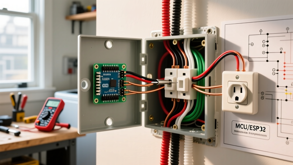
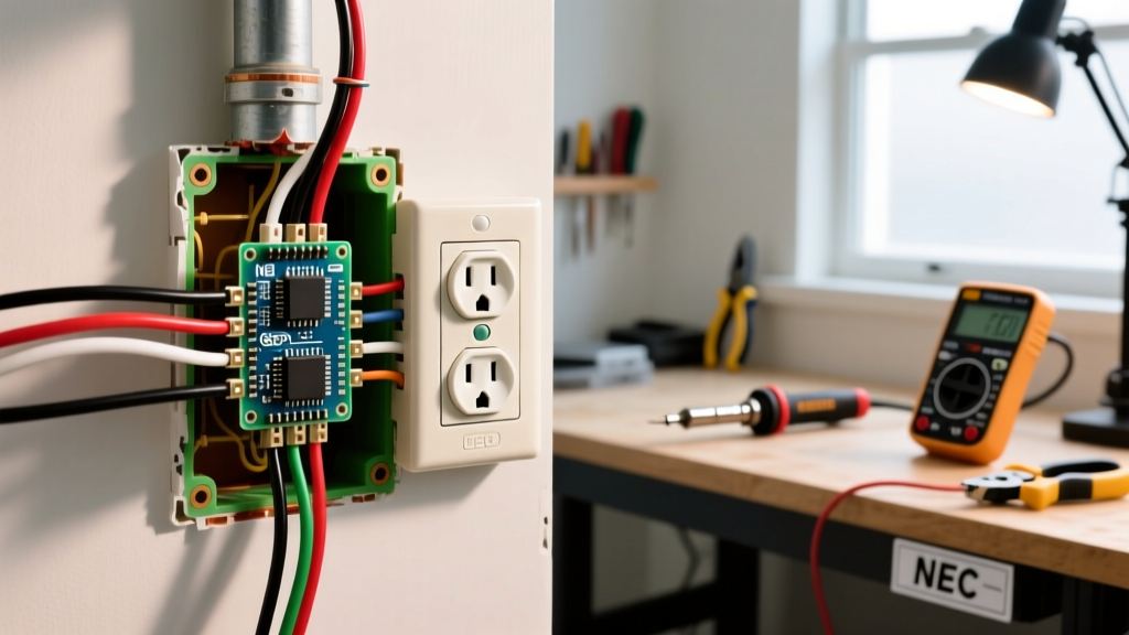
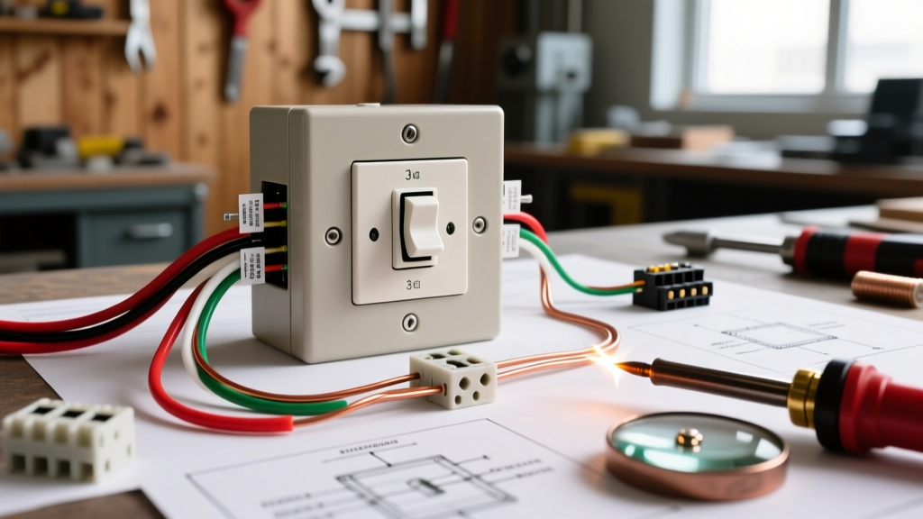
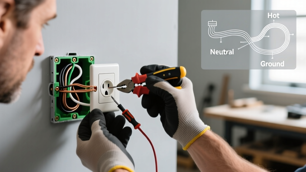
Homeowners, DIYers, and apprentice electricians frequently ask, "how do you wire an electrical outlet?" The standard answer is straightforward: connect the black (hot) wire to the brass terminal, the white (neutral) wire to the silver terminal, and the bare or green (ground) wire to the green grounding screw. However, the real challenge in residential and commercial electrical work isn't just making the connections—it is diagnosing and correcting the catastrophic mistakes left behind by previous installers.
According to the U.S. Consumer Product Safety Commission (CPSC), faulty electrical receptacles and improper wiring are leading causes of residential arc faults and electrical fires. In 2026, with the widespread enforcement of the latest National Electrical Code (NEC) revisions, understanding how to troubleshoot outlet wiring is just as critical as knowing how to install one from scratch. This guide shifts the focus from basic installation to advanced diagnostic troubleshooting, helping you identify hidden hazards that standard plug-in testers often miss.
Top 5 Outlet Wiring Mistakes & How to Diagnose Them
When an outlet fails, trips a breaker, or presents a shock hazard, the root cause is almost always a wiring error. Here are the five most dangerous mistakes and the exact diagnostic procedures to uncover them.
1. Reverse Polarity (Hot and Neutral Swapped)
The Mistake: The black hot wire is landed on the silver neutral terminal, and the white neutral wire is landed on the brass hot terminal. The outlet will still power a lamp, but the internal switch of the appliance now interrupts the neutral path rather than the hot path, leaving the appliance's internal components energized even when turned off.
Diagnosis: A standard 3-light receptacle tester (like the Klein Tools RT210) will illuminate the "Hot/Neu Reverse" LED pattern. To confirm, use a digital multimeter (DMM) set to AC voltage. Place the black probe on the brass screw and the red probe on the silver screw; a reading of -120V (or 120V with reversed leads) confirms the swap.
2. The "Bootleg Ground" Deception
The Mistake: In older homes lacking a true equipment grounding conductor, a lazy installer might place a jumper wire between the silver neutral terminal and the green ground screw. This tricks a standard 3-light tester into reading "Correct" because the tester completes its circuit through the neutral.
Diagnosis: This is a lethal hazard. If a hot wire shorts to the appliance chassis, the chassis becomes energized, and the breaker will not trip because there is no low-impedance ground path.
Expert Troubleshooting Tip: To diagnose a bootleg ground without removing the receptacle, measure the voltage between the hot slot and the ground slot, then measure between the hot slot and the neutral slot. If the ground slot reads exactly the same voltage as the neutral slot under load, or if a non-contact voltage tester detects voltage on the ground pin of a plugged-in cord, suspect a bootleg ground. Visual inspection behind the yoke is the only 100% confirmed diagnostic method.
3. Backstabbing vs. Side Wiring Failure Modes
The Mistake: Using the push-in "backstab" holes on the rear of 15A receptacles (such as the common Leviton T5262). These rely on a small internal spring-metal wedge to grip 14 AWG wire. Over time, thermal cycling from high-draw appliances (like vacuums or space heaters) causes the spring to relax, increasing resistance and generating extreme heat.
Diagnosis: Symptoms include intermittent power, a melted plastic smell, or an outlet that feels warm to the touch. Thermal imaging cameras (like the FLIR ONE Pro) will show a distinct heat bloom at the back of the yoke. The fix requires cutting off the damaged wire, re-stripping 3/4 inch of insulation using a Klein 11055, and using the side-binding screw terminals or screw-and-clamp (Spec-Grade) mechanisms.
4. Multi-Wire Branch Circuit (MWBC) Tab Errors
The Mistake: Kitchen and bathroom countertops often use MWBCs, where a single 12/3 or 14/3 cable feeds a duplex receptacle with two different 120V phases (one red, one black) sharing a single white neutral. The brass hot-side tab must be broken off. If the installer forgets to snap the tab, connecting the two opposing phases creates a 240V dead short.
Diagnosis: The breaker trips instantly with a loud pop upon reset, and the receptacle may show scorch marks. Always verify the presence of a red wire in the box; if found, the brass tab must be removed.
5. GFCI Line/Load Reversal
The Mistake: Ground Fault Circuit Interrupter (GFCI) receptacles have distinct LINE (incoming power) and LOAD (downstream protection) terminals. Wiring the incoming power to the LOAD terminals is a classic error.
Diagnosis: The GFCI will not power up, and the "Reset" button will feel mushy or fail to latch. Conversely, if incoming power is correctly on LINE, but downstream outlets are wired to LINE instead of LOAD, the downstream outlets will function but will lack ground-fault protection. Always use a DMM to identify the live incoming wires before terminating a GFCI.
Diagnostic Tool Matrix: Choosing the Right Tester
Professional diagnosis requires moving beyond the $5 plug-in cube testers. Below is a comparison of industry-standard diagnostic tools for outlet troubleshooting in 2026.
| Tool Model | Type | Approx. Cost | Best Diagnostic Use Case |
|---|---|---|---|
| Klein Tools RT210 | 3-Light Plug-In Tester | $22 | Quick polarity and open ground checks; basic GFCI trip testing. |
| Amprobe INSP-3 | Advanced Receptacle Tester | $45 | Measures actual GFCI trip time in milliseconds; detects voltage drop and wiring impedance. |
| Fluke T6-1000 | FieldSense Multimeter | $260 | Non-contact voltage and current measurement; diagnosing loose neutrals and shared-load imbalances without removing the outlet. |
| CDI 401SM | Torque Screwdriver | $130 | Verifying terminal torque to meet NEC 110.14(D) requirements; preventing thermal failure from loose screws. |
Step-by-Step Diagnostic Workflow for Suspect Outlets
When called to troubleshoot a failing or suspect receptacle, follow this systematic workflow to ensure safety and code compliance:
- De-energize and Verify: Turn off the circuit breaker. Use a non-contact voltage tester (NCVT) and a DMM to confirm 0V between hot-neutral, hot-ground, and neutral-ground.
- Extract and Inspect: Remove the receptacle from the electrical box. Do not pull by the wires. Inspect the wire insulation for heat damage (brittle, discolored, or melted sheathing). If found, the wire must be cut back to clean copper.
- Check for Bootlegs and Pigtails: Look for unauthorized jumper wires between neutral and ground. Ensure that if multiple cables enter the box, they are properly pigtailed using UL-listed wire nuts (like Ideal WireNuts) or Wago 221 series lever connectors, rather than "double-lugging" two wires under a single terminal screw.
- Verify Torque Specifications: The National Fire Protection Association (NFPA) mandates in NEC Article 110.14(D) that terminals must be tightened to the manufacturer's specified torque. For a standard Hubbell HBL5262 20A commercial receptacle, this is typically 14 in-lbs. Use a calibrated torque screwdriver to verify.
- Test Under Load: Re-energize the circuit. Plug in a known resistive load (like a 1500W space heater) and measure the voltage at the receptacle. A voltage drop of more than 3% to 5% (below 114V on a 120V circuit) indicates a loose connection upstream, often at a backstabbed outlet earlier in the daisy chain.
NEC Code Compliance & Safety Warnings
When diagnosing and repairing outlets, you must adhere to current electrical codes. The Occupational Safety and Health Administration (OSHA) strictly enforces wiring design and protection standards in commercial environments, which heavily mirror residential NEC requirements.
- Tamper-Resistant (TR) Mandate: All 15A and 20A, 125V and 250V non-locking receptacles in residential dwellings must be TR type. If you diagnose a standard receptacle in a modern home's living space, it is a code violation and must be replaced.
- AFCI/GFCI Dual Protection: In areas like kitchens, laundry rooms, and garages, outlets require both Ground Fault and Arc Fault protection. Diagnosing a nuisance trip requires determining if the fault is a ground leakage (GFCI) or a parallel arcing condition (AFCI). Modern dual-function circuit breakers provide diagnostic LED codes to differentiate these faults.
- Box Fill Calculations: A common cause of outlet failure is physical stress on the terminals caused by cramming too many wires into an undersized junction box. Always verify box fill capacity (NEC Article 314.16) when adding pigtails during a repair.
Frequently Asked Questions (FAQ)
Why does my outlet spark when I plug something in?
A small blue spark is normal when plugging in a high-draw appliance that is already turned "on" (like a vacuum or power tool) due to inrush current. However, a large yellow/orange spark accompanied by a pop indicates a loose connection, a short circuit, or degraded internal brass contacts. The receptacle should be replaced immediately with a commercial-grade model.
Can I use a 20A receptacle on a 15A circuit?
No. While you can install a 15A receptacle on a 20A circuit (provided it's a duplex receptacle per NEC 210.21(B)(3)), you cannot install a 20A receptacle (identified by the T-slot neutral) on a 15A breaker. The breaker would not trip before the receptacle's internal bus bar is overwhelmed if a 20A appliance is utilized.
What is the correct wire stripping length for side wiring?
Most modern 15A and 20A duplex receptacles feature a "strip gauge" molded into the back of the yoke. Typically, this is 3/4 of an inch (19mm). Stripping too little leaves exposed copper outside the terminal washer, creating a shock hazard. Stripping too much leaves bare copper exposed, risking a short against the metal junction box.