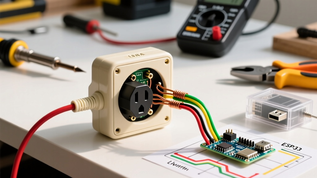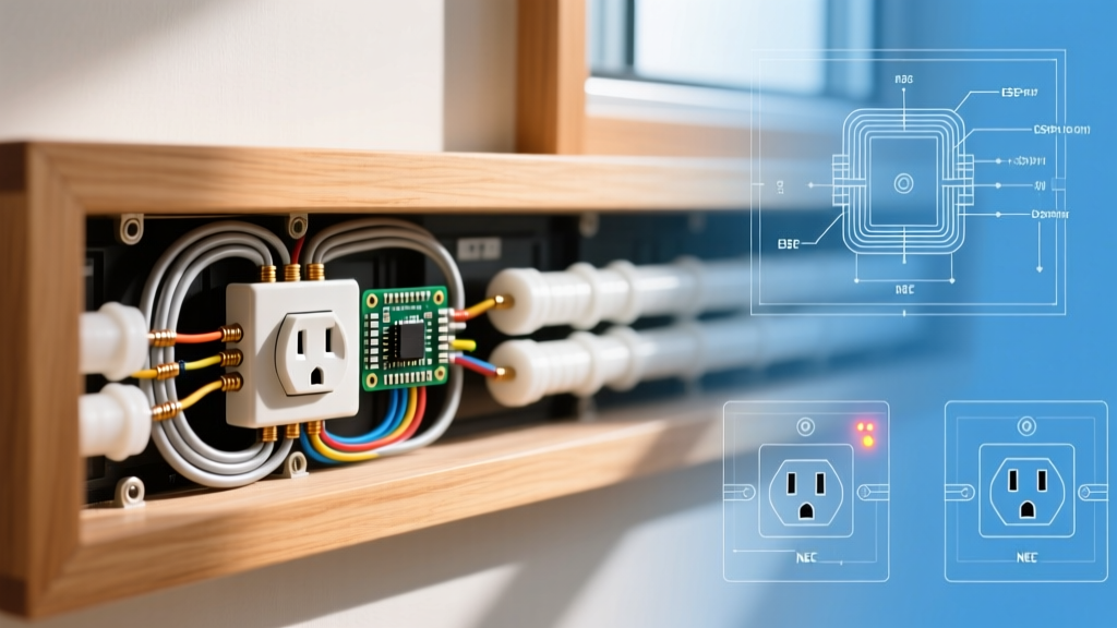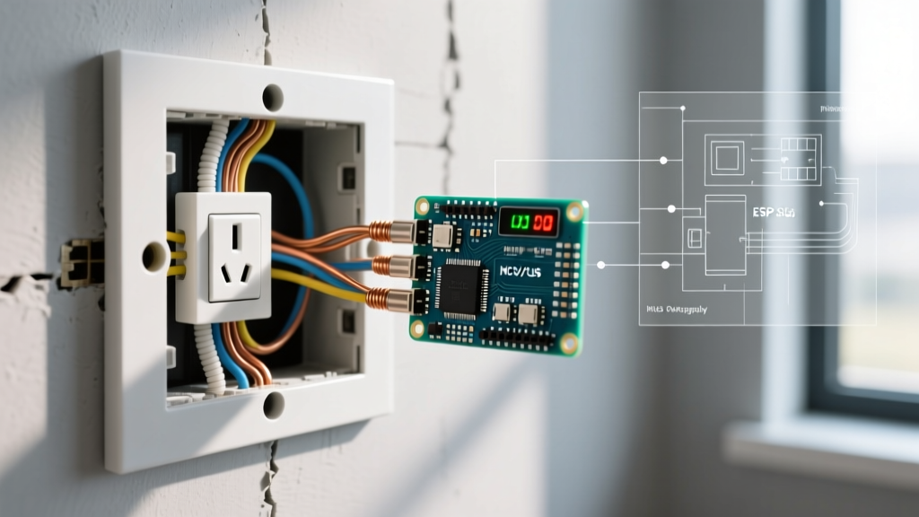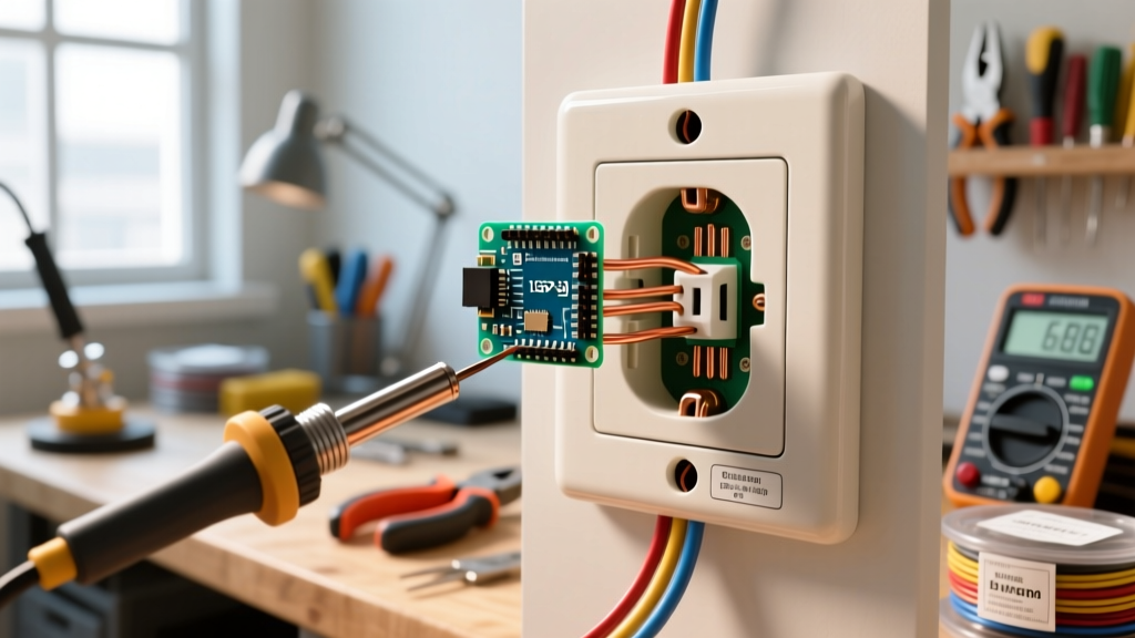

Introduction to the Electrical Outlet Pigtail
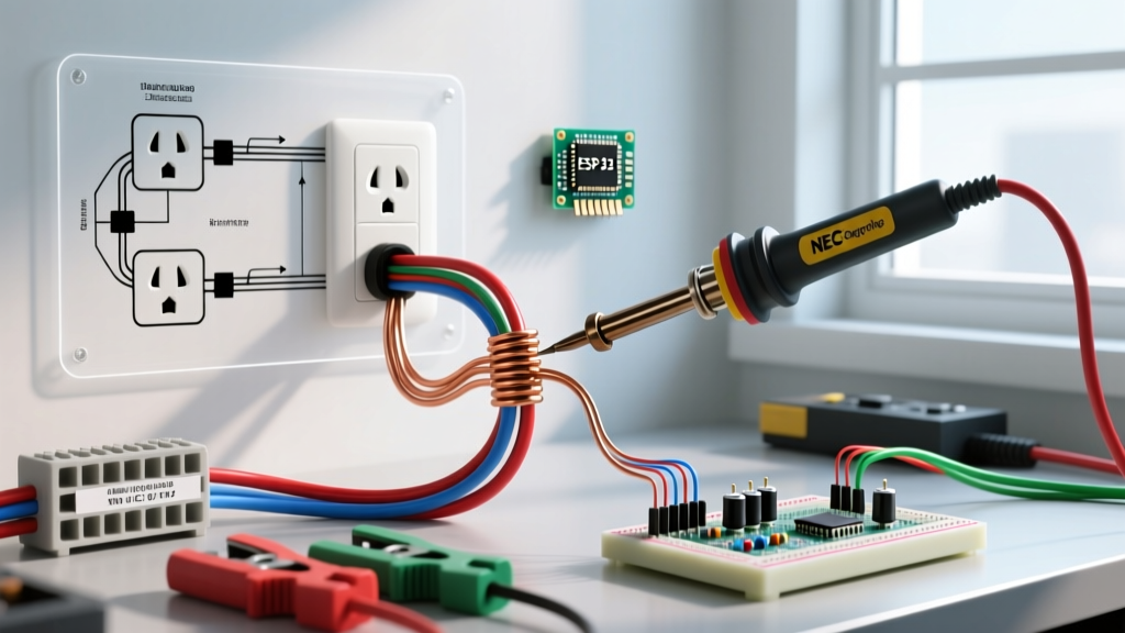
In residential and commercial electrical wiring, how you terminate conductors at a receptacle dictates the long-term safety and reliability of the entire circuit. While daisy-chaining (passing power through the receptacle's secondary terminals) is common, the electrical outlet pigtail remains the gold standard for safety, troubleshooting, and strict adherence to the National Electrical Code (NEC). An electrical outlet pigtail involves using a short jumper wire to connect the incoming and outgoing circuit wires via a wire connector, with only the single jumper wire terminating directly on the receptacle screw terminal.
This guide explores the critical code-compliance scenarios where pigtailing is not just a best practice, but a mandatory requirement, and provides a master-level installation workflow for modern 2026 electrical standards.
NEC Code Compliance: When Pigtailing is Mandatory
While the NEC does not universally ban daisy-chaining on standard single-circuit receptacles, there are specific, high-risk scenarios where an electrical outlet pigtail is strictly enforced by code inspectors and safety professionals.
1. Multi-Wire Branch Circuits (MWBCs) and NEC 300.13(B)
The most critical application for pigtailing occurs on Multi-Wire Branch Circuits. An MWBC consists of two ungrounded (hot) conductors sharing a single grounded (neutral) conductor. Because the two hot legs are 180 degrees out of phase, the shared neutral only carries the unbalanced load.
Critical Safety Warning: If you daisy-chain the neutral wire through a duplex receptacle on an MWBC and later remove that receptacle for replacement, you break the neutral continuity. This forces the two 120V hot legs into a 240V series circuit, sending 240V directly into downstream 120V electronics, causing catastrophic equipment failure and severe fire hazards. NFPA 70 (NEC) Section 300.13(B) explicitly requires that the continuity of the grounded conductor in an MWBC must not depend on device connections. You must pigtail the neutral.
2. Grounding Conductor Continuity (NEC 250.148)
Similar to the MWBC neutral rule, grounding conductors must maintain continuity independent of the device. If multiple grounding wires enter the box to feed downstream devices, they must be spliced together with a pigtail to the receptacle's green grounding screw. Relying on the receptacle's mounting yoke or internal strap for ground continuity is a code violation and a major shock hazard.
3. AFCI and GFCI Load-Side Limitations
When wiring downstream receptacles off the LOAD terminals of a GFCI or AFCI device, the physical space inside the electrical box becomes severely constrained. While not always explicitly banned, daisy-chaining multiple wires under the tiny LOAD terminals of a modern GFCI receptacle often violates the manufacturer's listing instructions (which NEC 110.3(B) enforces). Pigtailing keeps the connections organized and ensures proper torque.
Daisy-Chaining vs. Pigtailing: A Structural Comparison
| Feature | Daisy-Chaining (Pass-Through) | Electrical Outlet Pigtail |
|---|---|---|
| Downstream Reliance | Downstream devices lose power if the receptacle is removed or fails. | Downstream devices retain power; only the local receptacle is isolated. |
| Box Fill Impact | Wires count as passing through (1 volume allowance per wire). | Pigtails originating and terminating in the box do not count toward box fill. |
| Troubleshooting | Difficult; requires testing at multiple downstream nodes to find an open. | Easy; localized connections are visible and testable in a single box. |
| MWBC Compliance | Illegal for the neutral conductor (NEC 300.13(B)). | Mandatory and fully code-compliant. |
| Terminal Stress | High; two wires under one screw or backstabbed can loosen over time. | Low; only one wire terminates on the device screw. |
Essential Tools and Materials for Modern Installations
To execute a professional-grade electrical outlet pigtail, abandon outdated habits and utilize modern, UL-listed materials designed for long-term thermal stability.
- Conductors: 12 AWG or 14 AWG solid copper THHN/THWN-2 wire (must match the circuit breaker rating and existing branch circuit wire gauge).
- Connectors: Wago 221-413 Lever-Nuts (rated for 20A/600V, accommodating up to 3 conductors) or Ideal 72B Twister wire nuts. Lever connectors are highly recommended in 2026 for their visual confirmation of wire seating and resistance to thermal cycling loosening.
- Stripping Tool: Klein Tools 11055 (for 14-10 AWG) to ensure exact strip lengths without nicking the copper.
- Torque Screwdriver: Klein Tools 7035 or similar, calibrated to the receptacle manufacturer's specified inch-pound rating (usually 14-16 in-lbs for standard 15A/20A duplex receptacles).
- Voltage Tester: Fluke 117 True-RMS Multimeter or a CAT III Non-Contact Voltage Tester (NCVT).
Step-by-Step Guide to Wiring an Electrical Outlet Pigtail
Follow this precise workflow to ensure your pigtail installation meets both code requirements and best practices for mechanical durability.
Step 1: Verify Power and Prepare the Box
Shut off the circuit breaker. Use your Fluke multimeter to test between the hot and neutral, and hot and ground, confirming 0V. Ensure the electrical box has adequate volume. Per NEC Article 314.16, a standard 15A/20A receptacle requires a specific cubic inch allowance. Remember: the incoming hot, incoming neutral, outgoing hot, and outgoing neutral each count as one conductor fill. The pigtails themselves (which do not leave the box) do not add to the box fill calculation.
Step 2: Cut and Strip the Pigtails
Cut three 6-inch lengths of solid copper wire (matching the circuit gauge: 12 AWG for 20A, 14 AWG for 15A).
Strip Lengths:
- For Wago 221 Lever Connectors: Strip exactly 11mm (7/16 inch). The housing has a built-in strip gauge.
- For Twist-On Wire Nuts: Strip 3/4 inch to ensure the insulation sits flush with the bottom of the nut and no bare copper is exposed below the skirt.
Step 3: Splice the Grounding Conductors
Group the bare copper (or green) incoming and outgoing ground wires with your ground pigtail. If using a standard wire nut, twist clockwise until tight. Give each wire a firm pull test. Connect the free end of the ground pigtail to the green grounding screw on the receptacle. Torque to manufacturer specifications.
Step 4: Splice the Neutral (White) Conductors
Insert the incoming white wire, outgoing white wire, and the white neutral pigtail into a Wago 221-413 lever connector. Close the levers. The transparent housing allows you to visually verify that all three wires are fully seated against the backstop. Terminate the pigtail to the silver (neutral) terminal screw.
Step 5: Splice the Hot (Black/Red) Conductors
Repeat the exact process from Step 4 using the black (or red) hot wires. Terminate the hot pigtail to the brass (hot) terminal screw. Never use the backstab (push-in) connections on the back of the receptacle; always use the side terminal screws with a proper J-hook or torque screwdriver for a gas-tight mechanical bond.
Step 6: Neatly Fold and Secure
NEC 300.14 requires at least 6 inches of free conductor length measured from the point the wire enters the box. To fold the wires into the box without pinching or damaging the insulation, push the wire connectors into the back corners of the box first, followed by the grounding bundle, and finally the receptacle. Secure the receptacle to the box using the provided 6-32 machine screws.
Common Failure Modes and Edge Cases
Even experienced electricians make mistakes when pigtailing. Avoid these critical failure modes:
- Mismatched Wire Gauges: Never use a 14 AWG pigtail on a 12 AWG 20-amp circuit. The pigtail becomes a bottleneck and a potential fire hazard if a downstream fault occurs. Always match the branch circuit gauge.
- Overfilled Boxes: Pigtailing requires wire connectors, which take up physical space. If you are working in a shallow 14-cubic-inch plastic nail-on box, adding lever nuts may exceed the box fill capacity, causing the drywall to bulge or the wires to be crushed. Upgrade to a deep 22-cubic-inch box if necessary.
- The "Backstab" Pigtail: Some installers create a pigtail but then push it into the backstab hole of the receptacle to save time. Backstab connections rely on a small internal spring that loses tension over time due to thermal expansion and contraction, leading to arcing and melted receptacles. Always use the side terminal screws.
Frequently Asked Questions
Do I need to pigtail the ground wire if there is only one cable entering the box?
If only one NM-B cable enters the box and terminates at the receptacle, NEC 250.148 allows you to connect the single ground wire directly to the receptacle's green screw without a pigtail. However, if the ground is continuing downstream to another box, you must splice and pigtail.
Can I use the brass terminal screws to daisy-chain instead of pigtailing?
On a standard, single-circuit branch (not an MWBC), you can land the incoming hot on the top brass screw and the outgoing hot on the bottom brass screw, provided the metal break-off tab between them is left intact. However, pigtailing is vastly superior because it prevents downstream power loss if the receptacle fails or is removed for painting/replacement.
Are Wago lever nuts code-compliant for pigtailing inside a receptacle box?
Yes. Wago 221 series connectors are UL 1588 listed and fully compliant with NEC 110.14 for splicing conductors. They are widely preferred by inspectors and professionals in 2026 due to their reliability and ease of use in cramped junction boxes.