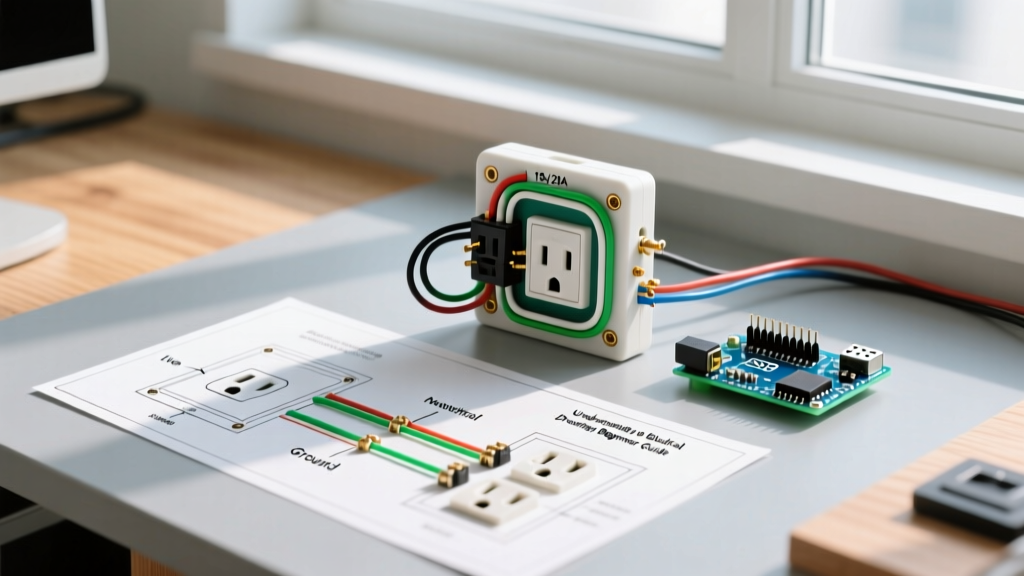

Decoding the Symbols in a Standard Electrical Outlet Drawing
When you first unroll a set of residential blueprints or look at a DIY wiring schematic, an electrical outlet drawing can seem like an arcane language of circles, lines, and letters. However, understanding these diagrams is the foundational skill for any safe electrical installation. An electrical outlet drawing bridges the gap between the National Electrical Code (NEC) requirements and the physical reality of your wall box.
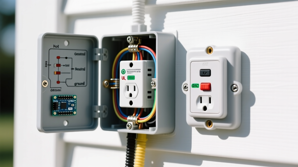
On a standard architectural blueprint, a duplex receptacle is typically represented by a circle with two parallel lines extending outward, often accompanied by a half-circle intersecting the main circle. If you see the letters GFI or GFCI next to the symbol, it indicates a Ground Fault Circuit Interrupter is required at that location—usually mandated for kitchens, bathrooms, garages, and outdoor areas. If the symbol has a triangle or the letters AFCI, it denotes an Arc Fault Circuit Interrupter requirement, common in bedrooms and living spaces.
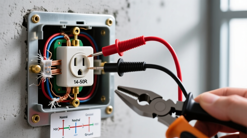
Safety Override: Never trust a breaker panel label. According to the Occupational Safety and Health Administration (OSHA), physical verification with a non-contact voltage tester (such as the Fluke 1AC-II VoltAlert) and a multimeter are mandatory steps before exposing any conductor or removing a wall plate.
15-Amp vs. 20-Amp Receptacle Diagrams: What the Drawing Tells You
One of the most critical pieces of information an electrical outlet drawing provides is the amperage and wire gauge required for the circuit. Misinterpreting this can lead to overheated wires and severe fire hazards. The National Fire Protection Association (NFPA) outlines strict rules in NEC Article 210 regarding branch circuit ratings and the corresponding receptacle configurations.
| Feature | 15-Amp Circuit (NEMA 5-15R) | 20-Amp Circuit (NEMA 5-20R) |
|---|---|---|
| Wire Gauge Required | 14 AWG Copper (Minimum) | 12 AWG Copper (Minimum) |
| Breaker Size | 15A | 20A |
| Receptacle Slot Design | Two parallel vertical slots | One vertical, one horizontal (T-slot) |
| Typical Device Cost (2026) | $2.50 - $4.00 | $4.00 - $7.50 |
| Common Use Cases | Bedrooms, living rooms, hallways | Kitchens, bathrooms, garage workbenches |
While you can install a 15-amp receptacle on a 20-amp circuit (provided there is more than one receptacle on the circuit), you can never install a 20-amp receptacle on a 15-amp circuit. The drawing will specify the circuit rating, dictating which NEMA configuration you must purchase.
Step-by-Step: Translating the Drawing to Physical Installation
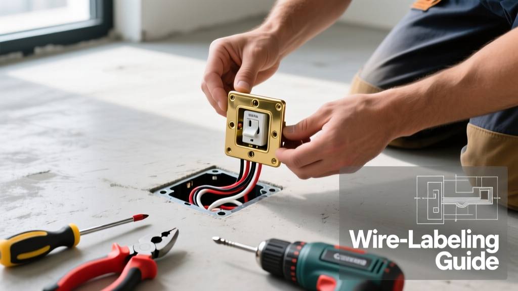
Once you understand the schematic, it is time to execute the physical wiring. Most basic electrical outlet drawings show the hot (black), neutral (white), and ground (bare/green) wires connecting directly to the receptacle. Here is how to translate that drawing into a code-compliant, durable installation using a standard 15A tamper-resistant receptacle like the Leviton T5280-W.
- Prepare the Conductors: Using a precision wire stripper like the Klein Tools 11055, strip exactly 3/4 inch of insulation from the solid copper wires. Stripping too little leaves exposed bare wire outside the terminal; stripping too much leaves bare copper exposed inside the box, risking a short circuit.
- Form the J-Hook: Use needle-nose pliers to bend the bare end of the wire into a tight 'J' shape or shepherd's hook. The hook must be oriented clockwise. When you tighten the terminal screw, the clockwise rotation will pull the loop tighter around the screw shaft rather than pushing it out.
- Make the Connections: Connect the black (hot) wire to the brass screw, the white (neutral) wire to the silver screw, and the bare copper (ground) to the green grounding screw.
- Torque the Terminals: While many DIYers hand-tighten screws until they feel 'snug', commercial electricians use torque screwdrivers. The internal brass threads can strip if over-torqued, leading to a loose connection that arcs over time. Tighten firmly until the wire is seated flat and cannot be pulled out with a gentle tug.
- Fold and Mount: Carefully fold the wires in a Z-pattern into the back of the electrical box, ensuring no bare ground wires are touching the hot brass terminals. Mount the device using the provided 6-32 mounting screws, ensuring the yoke sits flush against the drywall.
The 'Backstabbing' Failure Mode: What Drawings Don't Show
Most beginner electrical outlet drawings do not explicitly warn against a common installation shortcut: backstabbing. Many modern receptacles feature push-in holes on the back of the device designed to accept 14 AWG wire without forming a J-hook.
While technically UL-listed, experienced electricians overwhelmingly avoid backstabbing for standard residential devices. The internal spring-loaded contacts grip the wire with minimal surface area. Over years of thermal cycling—where the wire heats up under load and cools down when idle—the metal expands and contracts. This gradually loosens the spring grip, increasing electrical resistance. High resistance generates excessive heat, which can melt the plastic receptacle housing and cause a fire. Always default to the side-wiring (terminal screw) method shown in professional schematics, or use commercial-grade receptacles that feature screw-clamp back-wiring plates that physically trap the wire under a metal plate.
GFCI and Multi-Outlet Circuit Drawings Explained
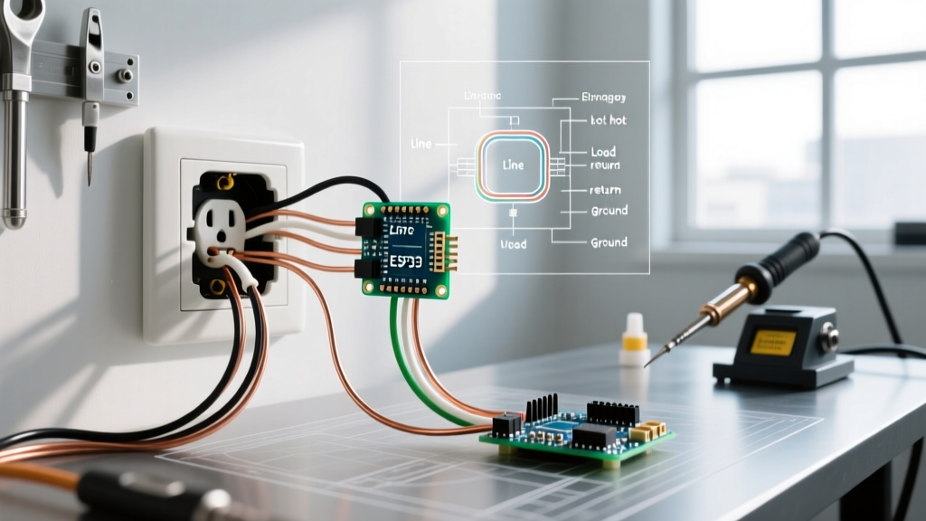
When your electrical outlet drawing includes multiple receptacles downstream from a single GFCI device, the schematic will introduce the concepts of Line and Load. This is where many beginners make critical errors.
- Line Terminals: These connect directly to the incoming power source from the breaker panel. If you wire power to the Load terminals by mistake, the GFCI will still power the outlet, but the ground-fault protection will be completely disabled, creating a severe shock hazard.
- Load Terminals: These are used to feed power to downstream standard receptacles, extending the GFCI protection to other outlets in the wet area. If your drawing shows a GFCI protecting a downstream bathroom vanity outlet, the wires leaving the GFCI to feed the next box must be connected to the Load terminals.
Furthermore, the U.S. Consumer Product Safety Commission (CPSC) strongly recommends pigtailing wires when connecting multiple cables in a single box, rather than daisy-chaining the neutral and hot wires through the receptacle terminals. Pigtailing ensures that if one receptacle fails or is removed for replacement, the downstream outlets do not lose their neutral return path, which can cause dangerous voltage fluctuations on multi-wire branch circuits.
Essential Tools for the Job
To execute the wiring diagram accurately and safely, ensure your toolkit includes:
- Non-Contact Voltage Tester: Fluke 1AC-II (Approx. $35)
- Wire Strippers: Klein Tools 11055 (Approx. $28)
- Lineman Pliers: Knipex 01 26 200 (Approx. $55)
- Receptacle Tester: Gardner Bender GFI-3501 to verify wiring sequence post-installation (Approx. $15)
Frequently Asked Questions
Why does my drawing show a switched outlet with a broken fin?
If the electrical outlet drawing indicates a half-hot receptacle (where the top plug is controlled by a wall switch and the bottom is always on), you must use a needle-nose plier to snap off the small brass connecting fin on the hot side of the receptacle. This isolates the top and bottom brass terminals, allowing you to feed constant power to one and switched power to the other. Do not break the silver fin on the neutral side.
Can I use 12 AWG wire on a 15-amp receptacle?
Yes. While 14 AWG is the minimum for 15-amp circuits, using 12 AWG wire is perfectly safe and actually reduces voltage drop over long distances. However, 12 AWG wire is thicker and stiffer, making it slightly more difficult to fold into standard single-gang boxes. Ensure your electrical box has adequate cubic inch volume (at least 18 cubic inches for multiple 12 AWG conductors) to meet NEC box-fill calculations.