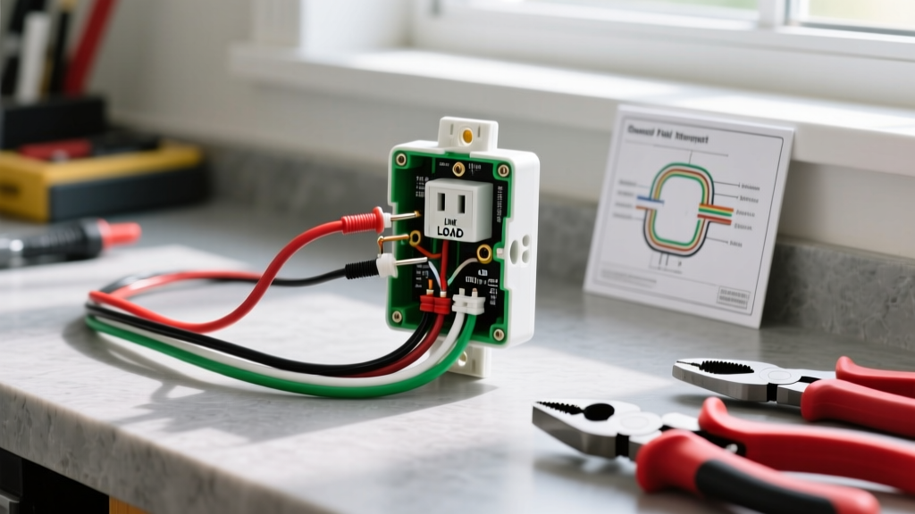

Understanding the GFI Electrical Outlet
When working in areas where water and electricity intersect, standard receptacles are no longer sufficient. A gfi electrical outlet (more formally known in the industry as a Ground Fault Circuit Interrupter, or GFCI) is a critical safety device designed to protect against lethal electric shocks. By continuously monitoring the current balance between the hot and neutral conductors, a GFCI can detect a ground fault as small as 4 to 6 milliamps and trip the circuit in as little as 20 to 30 milliseconds.
While the National Electrical Code (NEC) and the U.S. Consumer Product Safety Commission (CPSC) mandate GFCI protection in wet locations, many homeowners attempt DIY installations without understanding the critical distinction between LINE and LOAD terminals. This guide provides a deep-dive, professional-grade walkthrough for wiring a GFI electrical outlet correctly the first time.
GFI vs. Standard Receptacles vs. AFCI
Before pulling any wires, it is vital to understand what you are installing. A standard duplex receptacle offers no internal fault protection. An AFCI (Arc Fault Circuit Interrupter) protects against electrical fires caused by arcing. A GFI electrical outlet specifically protects humans from electrocution. In modern 2026 electrical panels, you may also encounter Dual Function (DF) receptacles that combine both AFCI and GFCI protection, typically costing between $35 and $45, compared to $15 to $25 for a standard 15-Amp GFCI like the Leviton SmartLockPro Slim GFNT1-W.
Tools and Materials Required
Professional results require professional tools. Do not attempt this installation with dull wire strippers or uncalibrated testers.
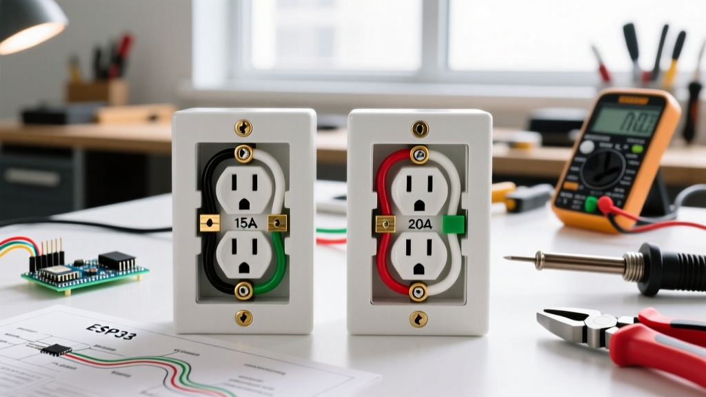
- GFCI Receptacle: 15-Amp or 20-Amp rated (e.g., Eaton GFTR15-W or Leviton GFNT1-W). Match the amperage to your circuit breaker.
- Non-Contact Voltage Tester (NCVT): Klein Tools NCVT-2 (dual-range 12-1000V AC).
- Digital Multimeter: For verifying exact voltage and identifying LINE/LOAD.
- Wire Strippers: Klein Tools 11063W (Katapult) for clean 12 AWG and 14 AWG strips.
- Torque Screwdriver: Klein Tools 70555. Crucial for meeting modern NEC torque specifications.
- Electrical Tape: 3M Super 33+ (for wrapping the device sides if using side-wiring).
The Golden Rule: LINE vs. LOAD Terminals
The most common failure mode in DIY GFI electrical outlet installations is reversing the LINE and LOAD wires. The device will appear to work (it will provide power), but it will not provide ground fault protection, leaving users vulnerable to fatal shocks.
Expert Callout: Decoding the Terminals
LINE Terminals (Usually marked with black tape or 'LINE' text): These connect to the wires bringing power from the breaker panel. This is your power source.
LOAD Terminals (Usually covered by a yellow warning sticker): These connect to wires carrying power downstream to protect additional standard outlets on the same circuit.
Note: If your electrical box only has one set of wires (one black, one white, one ground), you are at the 'end of the run.' Connect these wires ONLY to the LINE terminals. Leave the LOAD terminals empty and keep the yellow sticker intact.
Step-by-Step Installation Guide
Step 1: De-energize and Verify (LOTO Protocol)
Turn off the corresponding 15A or 20A breaker at the main service panel. For maximum safety, apply a Lockout/Tagout (LOTO) device to the breaker to prevent accidental re-energizing. Use your NCVT to test the existing receptacle. Follow up with a digital multimeter set to AC Voltage (V~), probing from the hot slot to the neutral slot, and hot to ground. The reading must be exactly 0.0V.
Step 2: Identify LINE and LOAD Conductors
If your wall box contains multiple cables (e.g., two Romex cables entering the box), you must identify which is the LINE (power feed) and which is the LOAD (downstream feed).
- Carefully separate the wires so they do not touch each other or the metal box.
- Temporarily turn the breaker back on.
- Use your NCVT to identify the hot wire in Cable A and Cable B.
- The cable that registers voltage is your LINE. The cable with no voltage is your LOAD.
- Turn the breaker back off and re-verify with your multimeter.
Step 3: Prepare the Conductors
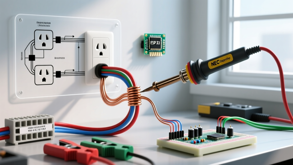
Strip the wire insulation to the exact length required by the manufacturer's strip gauge, usually located on the back of the GFI electrical outlet. For 14 AWG wire, this is typically 5/8 inch. For 12 AWG wire, it is usually 3/4 inch. Do not nick the copper conductor, as this creates a weak point that can snap under terminal torque or cause localized heating.
Step 4: Terminate the Connections
We strongly recommend using the side-wiring terminal screws rather than the back-stab (push-in) holes, which are notorious for loose connections and arcing over time.
- LINE Hot (Black): Connect to the Brass screw marked LINE.
- LINE Neutral (White): Connect to the Silver screw marked LINE.
- LOAD Hot (Black): Connect to the Brass screw marked LOAD (if feeding downstream).
- LOAD Neutral (White): Connect to the Silver screw marked LOAD (if feeding downstream).
- Ground (Bare/Green): Connect to the Green grounding screw on the device, and ensure the box is also grounded via a pigtail if it is a metal enclosure.
Step 5: Apply Proper Torque
According to recent updates in the National Fire Protection Association (NFPA) NEC guidelines, terminal screws must be tightened to the manufacturer's specified torque. Use a calibrated torque screwdriver set to 14 in-lbs (standard for most 15A/20A Leviton and Eaton GFCIs). This prevents the 'cold flow' of copper, which causes screws to loosen over years of thermal expansion and contraction.
Step 6: Secure and Test
Carefully fold the wires into the box using a 'Z-fold' or 'accordion' method to avoid pinching the conductors against the metal strap. Screw the GFI electrical outlet into the box, ensuring it sits flush. Attach the cover plate. Restore power at the breaker.
Press the TEST button on the receptacle. You should hear a distinct 'click,' and the reset button should pop out. Plug in a lamp or voltage tester to confirm power is dead. Press the RESET button to restore power. If the device will not reset, or if it trips immediately upon resetting, you have a wiring fault or a ground fault downstream.
Troubleshooting Common GFI Wiring Failures
Even experienced electricians encounter anomalies. Use this diagnostic matrix to resolve issues quickly.
| Symptom | Probable Cause | Corrective Action |
|---|---|---|
| Outlet provides no power; Reset button will not stay in. | LINE and LOAD wires are reversed, or power is not reaching the LINE terminals. | Verify power source. Swap LINE and LOAD connections if power is confirmed on the wrong set. |
| Outlet works, but downstream outlets are dead. | LOAD wires disconnected, or downstream neutral is not tied to the GFCI LOAD terminal. | Ensure downstream white wire is on the LOAD Silver screw, not pigtailed to the LINE neutral. |
| GFCI trips immediately upon reset. | Actual ground fault downstream, or shared neutral (multi-wire branch circuit). | Disconnect LOAD wires. If GFCI holds, the fault is downstream. Check for shared neutrals, which require a 2-pole GFCI breaker instead. |
| GFCI trips randomly when heavy appliances run. | Nuisance tripping due to capacitive leakage or long cable runs. | Upgrade to a high-surge-immunity GFCI model (e.g., Leviton GFNT2) designed to filter out transient voltage spikes. |
2026 NEC Code Requirements and Best Practices
The NEC continually expands the mandate for GFCI protection. As of the latest code cycles enforced in 2026, a gfi electrical outlet (or GFCI breaker) is required in all 125-volt through 250-volt receptacles supplied by single-phase branch circuits rated 150 volts or less to ground, 50 amperes or less, in the following locations:
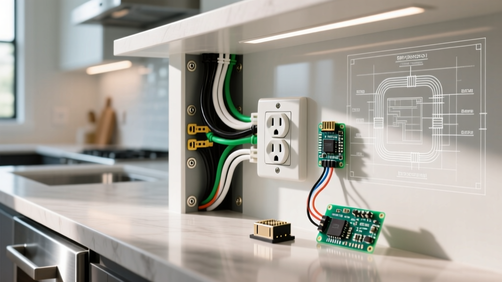
- Bathrooms and Kitchens (all countertop receptacles)
- Garages, accessory buildings, and crawlspaces
- Outdoors (including balconies and decks)
- Laundry areas, utility sinks, and wet bar sinks
- Dishwashers (a relatively recent addition that catches many DIYers off guard during kitchen remodels)
Pro-Tip for Older Homes: If you are installing a GFCI in an older home with a two-wire system (no equipment grounding conductor), the NEC allows you to install a GFCI receptacle to provide shock protection. However, you must label the faceplate with the included sticker reading 'GFCI Protected' and 'No Equipment Ground'. The GFCI will still trip and save a life in the event of a fault, even without a physical ground wire present.
Final Thoughts on Maintenance
Installation is only half the battle. The internal solid-state components of a GFI electrical outlet can degrade over time, especially in humid environments like outdoor enclosures or coastal regions. The CPSC and manufacturers recommend pressing the TEST button on every GFCI receptacle in your home at least once a month. If the device fails to trip, or if the reset button feels mushy and refuses to latch, the internal solenoid has failed. GFCIs are not serviceable; immediate replacement is the only safe corrective action.