
The Critical Role of the 7-Way Connector in Towing Safety
When towing a travel trailer, horse trailer, or flatbed equipped with electric brakes, the 7-way RV blade connector is the central nervous system of your rig. A flawed connection doesn't just mean dark running lights; it means a complete failure of your trailer's braking capacity under a 6,000-pound load. This inspection and testing guide breaks down the exact wiring diagram for trailer plug with brakes, providing a professional-grade diagnostic protocol to verify circuit integrity, measure voltage drop, and isolate pulse-width modulation (PWM) faults in modern brake controllers.
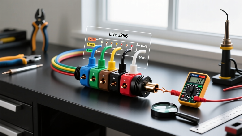
Standard SAE J286 Wiring Diagram for Trailer Plug with Brakes
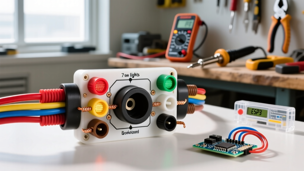
Before applying a multimeter probe, you must understand the standardized pinout. The recreational vehicle industry adheres to the SAE J286 and RVIA color-code standards for 7-way blade connectors. Below is the definitive matrix for the vehicle-side receptacle and trailer-side plug.
| Pin Position | Function | SAE Wire Color | Wire Gauge (Min) | Signal Type |
|---|---|---|---|---|
| Pin 1 (Top/Center) | Ground Return | White | 10 AWG | DC Ground (0V) |
| Pin 2 (Top Right) | Electric Brakes | Blue | 10 AWG | PWM DC (0-12V) |
| Pin 3 (Bottom Right) | Tail/Running Lights | Brown | 14 AWG | 12V DC Constant |
| Pin 4 (Bottom Left) | Left Turn/Stop | Yellow | 14 AWG | 12V DC Pulsed |
| Pin 5 (Center Left) | 12V Auxiliary Power | Black | 10 AWG | 12V DC Constant |
| Pin 6 (Center Right) | Right Turn/Stop | Green | 14 AWG | 12V DC Pulsed |
| Pin 7 (Bottom Center) | Backup Lights/Aux | Red (or Purple) | 14 AWG | 12V DC (Reverse) |
Required Diagnostic Tooling and 2026 Budget
Standard 12V test lights are obsolete for diagnosing modern towing setups. Modern brake controllers like the Tekonsha Prodigy P3 ($165) or Redarc Tow-Pro Liberty ($210) utilize Pulse Width Modulation (PWM) to send power to the brake magnets. An incandescent test light will not accurately read PWM duty cycles, leading to false diagnostics.
- True RMS Digital Multimeter: Fluke 117 ($210) or Klein Tools MM400 ($45). Essential for accurate PWM voltage readings.
- Circuit Tester and Load Simulator: Hopkins 40376 ($18) or Curt 57003 LED Load Resistors ($14) to simulate trailer draw.
- Dielectric Grease: Permatex 22058 ($6) for post-inspection weatherproofing.
Step-by-Step Inspection and Testing Protocol
Phase 1: Ground Integrity and Voltage Drop Testing
Over 70 percent of trailer wiring faults stem from Pin 1 (White Ground). A poor ground forces current to seek alternative paths, often backfeeding through the brake circuit or tail lights, causing erratic brake controller behavior.
- Resistance Check: Disconnect the trailer. Set your multimeter to Ohms. Place the black probe on a clean, bare metal spot on the trailer chassis and the red probe on Pin 1 of the trailer plug. A reading above 0.5 Ohms indicates corrosion or a loose crimp.
- Voltage Drop Test: Reconnect the trailer. Turn on the running lights (Pin 3). Measure DC voltage between the vehicle chassis ground and Pin 1 on the trailer side. A drop greater than 0.2V under load dictates that the 10 AWG white wire is compromised or the chassis grounding bolt is oxidized.
Phase 2: Electric Brake Circuit Load Testing (Pin 2)
The blue wire (Pin 2) carries the most critical safety signal. Because the brake controller outputs a PWM signal, the voltage fluctuates based on brake pedal pressure and controller gain settings.
- Set your True RMS multimeter to DC Volts.
- Connect the red probe to Pin 2 (Blue) and the black probe to Pin 1 (White/Ground).
- Have an assistant press the vehicle brake pedal fully while the engine is running to maintain alternator voltage above 13.5V.
- Observe the multimeter. A properly functioning controller set to maximum gain should output between 11.5V and 12.5V. If you read 0V, check the controller red stop-light switch wire. If you read a fluctuating 4V to 8V with the pedal fully depressed, the controller internal MOSFETs may be failing, or there is high resistance in the blue wire run.
Phase 3: Breakaway Switch and Auxiliary Verification
Test Pins 3, 4, 5, 6, and 7 using standard 12V DC testing. Pay special attention to Pin 5 (Black, 12V Aux). This circuit is often tied directly to the vehicle battery via a 40A breaker and is used to trickle charge the trailer breakaway battery. To test the breakaway system independently, pull the physical pin on the trailer breakaway switch. Measure voltage at the brake magnets themselves. You should read full battery voltage (12.5V+). If voltage drops below 10V, the breakaway battery is sulfated and will fail to lock the brakes during an uncoupling emergency.
Advanced Troubleshooting: Edge Cases and Failure Modes
Expert Insight: If your Tekonsha Prodigy P3 displays an S.H. (Short Circuit) code when you press the brake pedal, but a continuity test on the blue wire shows no dead short to ground, the issue is likely water ingress inside the 7-way plug casing creating a micro-short between Pin 2 and Pin 1 under high voltage. Disassemble the plug, clean with electrical contact cleaner, and pack with dielectric grease.
The LED Backfeed Phenomenon
In 2026, nearly all new trailers utilize LED lighting. LEDs draw a fraction of the current of incandescent bulbs (often 0.2A vs 2.1A). Some older or poorly designed vehicle tow modules interpret this low draw as a burned out bulb or fail to trigger the brake controller boost feature. Furthermore, cheap LED drivers can leak reverse-polarity voltage back into the turn signal circuits. If your brake controller activates slightly when you hit the turn signal, install a Curt 57003 load resistor on the turn signal circuits or upgrade to a smart PWM-compatible tow module like the Curt 56400.
Regulatory Compliance and Safety Standards
Proper trailer wiring is not just a best practice; it is a federal mandate for commercial and heavy-duty towing. According to the Federal Motor Carrier Safety Administration (FMCSA), all commercial trailers must comply with FMVSS 108 lighting and reflective device regulations, which strictly dictate the synchronization of stop lamps and turn signals FMCSA Title 49 Section 393.9. For recreational towers, adhering to SAE J286 ensures interoperability and prevents catastrophic brake failure on steep grades.
Furthermore, the National Highway Traffic Safety Administration (NHTSA) emphasizes that any modification to a vehicle factory lighting system, including the installation of aftermarket 7-way receptacles and brake controllers, must not degrade the original equipment manufacturer safety compliance NHTSA Vehicle Safety Guidelines. Always use heat-shrink butt connectors (minimum 120C rating) rather than standard vinyl crimps when repairing the wiring harness leading to your trailer plug to prevent moisture-induced galvanic corrosion.
For detailed diagnostic flowcharts specific to your vehicle OEM tow package, consult the Curt Manufacturing Troubleshooting Hub, which maintains an updated database of module-specific fault codes and wiring adaptations for late-model trucks and SUVs.