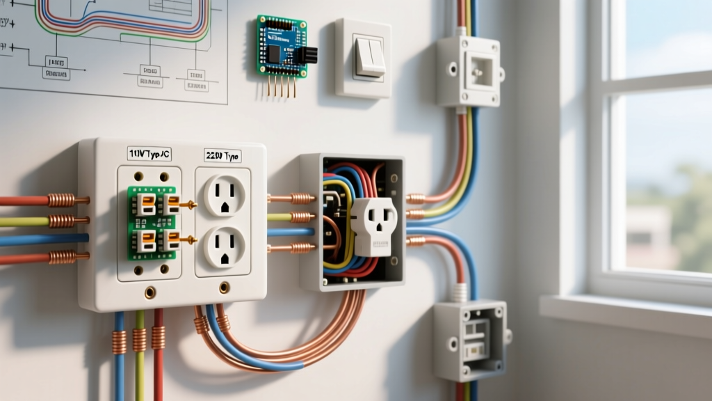

Decoding the Anatomy of a Dead Circuit
Before reaching for a screwdriver, it is critical to distinguish between terminology defined in the National Electrical Code (NEC) Article 100. An outlet is a point on the wiring system where current is taken to supply utilization equipment. A receptacle is the specific contact device installed at the outlet to accommodate a plug. When a homeowner says an "outlet is dead," they are almost always diagnosing a failed receptacle, a tripped upstream GFCI, or a severed branch-circuit conductor.
Troubleshooting electrical outlets and receptacles requires moving beyond simple plug-in testers. While a $10 neon tester can confirm basic polarity, it cannot identify high-resistance faults, shared-neutral conflicts, or ghost voltages induced by capacitive coupling. In 2026, modern diagnostics require a true-RMS multimeter and a systematic elimination process to ensure safety and code compliance.
Essential Diagnostic Tools for Receptacle Troubleshooting
To accurately diagnose branch circuit faults, you must equip yourself with tools that eliminate false positives and measure under actual load conditions.
- Fluke 117 True-RMS Multimeter ($200 - $220): Features a LoZ (Low Impedance) mode. This is mandatory for eliminating "ghost voltages"—stray capacitive voltages that can make a dead wire appear live on standard high-impedance meters.
- Klein Tools RT250 GFCI Receptacle Tester ($35 - $45): Unlike older models, the RT250 can verify ground wire integrity and trip standard GFCI receptacles without relying on the receptacle's internal test coil, which can fail silently.
- Wiha 12-Piece Insulated Torque Screwdriver Set ($140 - $160): NEC 110.14(D) strictly requires terminations to be torqued to the manufacturer's specifications. Hand-tightening leads to thermal creep and eventual open-circuit failures.
- FLIR C5 Thermal Imaging Camera ($500 - $550): Crucial for identifying high-resistance connections inside the junction box before they result in a melted faceplate or arc fault.
Top 5 Failure Modes of Electrical Outlets and Receptacles
When diagnosing a dead or malfunctioning receptacle, cross-reference the symptoms below to isolate the fault quickly.
| Symptom | Root Cause | Diagnostic Test | Estimated Fix Cost / Time |
|---|---|---|---|
| Dead Receptacle (No Voltage) | Open Neutral via Backstab Failure | Wiggle test; check continuity of neutral to ground | $5 (Receptacle) / 15 mins |
| 120V Floats to 200V-240V | Lost Shared Neutral on MWBC | Measure Line-Neutral at Panel; check neutral bus bar | $150+ (Electrician) / 1 hr |
| GFCI Nuisance Tripping | Shared Neutral Downstream | Disconnect load neutral; verify dedicated circuit | $10 (Re-wire) / 30 mins |
| Melted Faceplate / Discoloration | High Resistance / Loose Lug | Thermal Camera scan; Torque check terminals | $8 (Torque Driver) / 10 mins |
| Voltage Drop > 5% Under Load | Undersized Wire / Long Run | Measure voltage while drawing 15A (e.g., space heater) | $150+ (Rewire) / 2+ hrs |
Deep Dive: The Backstab Epidemic and Thermal Creep
The most common cause of a localized dead receptacle is the failure of push-in (backstab) wire connections. Standard 15A receptacles (like the Leviton 1620-PL) utilize spring-metal contacts to grip 14 AWG solid copper wire. Over time, the thermal expansion and contraction caused by high-draw appliances (like 1500W space heaters or vacuum cleaners) causes the copper wire to "creep" or loosen from the brass spring.
When this connection loosens, it creates a high-resistance fault. According to OSHA electrical safety guidelines, high resistance generates localized heat (I²R losses), which degrades the insulation and eventually leads to an open neutral or an arc fault. The Fix: Never use backstab connections for 12 AWG or 14 AWG wire. Always use the side-wire screw terminals, and torque the screws to the manufacturer's specification (typically 12 to 14 inch-pounds for standard 15A/20A devices).
Edge Case: Pre-1972 Aluminum Wiring
If you are troubleshooting an older home, you may encounter aluminum branch circuit wiring. The Consumer Product Safety Commission (CPSC) warns that aluminum wire manufactured before 1972 expands at a different rate than brass and copper, leading to severe thermal creep and oxidation at receptacle terminals. Standard copper-rated receptacles will cause a fire hazard if used with aluminum wire. You must either pigtail the aluminum wire to copper using King Innovation Alumiconn connectors (approx. $6 each) or install specialized CO/ALR rated receptacles.
GFCI and AFCI Nuisance Tripping Diagnosis
Ground Fault Circuit Interrupter (GFCI) and Arc Fault Circuit Interrupter (AFCI) receptacles are highly sensitive diagnostic tools in themselves. If a GFCI receptacle refuses to reset or trips immediately, do not simply replace the device. Investigate the following edge cases:
- The Shared Neutral Conflict: If a multi-wire branch circuit (MWBC) was improperly split, and the GFCI protects a downstream receptacle that shares a neutral with another circuit, the GFCI will detect the returning current from the second circuit as a ground fault and trip instantly. You must separate the neutrals in the junction box.
- UV and Moisture Degradation: Exterior GFCI receptacles (even those rated WR for Weather Resistant) suffer from UV degradation of the internal varistors and test coils. If an exterior Leviton or Eaton GFCI is over 7 years old and tripping during rain events, the internal potting compound has likely failed, allowing micro-condensation to bridge the sensing toroid. Replace the unit and ensure the in-use bubble cover is sealed with exterior-grade silicone.
- Capacitive Leakage in Long Cable Runs: AFCI breakers and receptacles can nuisance trip when long runs of UF-B (Underground Feeder) cable accumulate enough capacitive leakage to ground to mimic an arc signature. This is common in landscape lighting circuits tied to indoor receptacles.
CRITICAL SAFETY WARNING: Multi-Wire Branch Circuits (MWBC)
Before removing any receptacle to troubleshoot it, verify if it is part of an MWBC (two hot wires on different phases sharing a single neutral). If you disconnect the neutral wire on an active MWBC without turning off both breakers, the 120V appliances on the opposing phase will suddenly be forced into a 240V series circuit, instantly destroying electronics and creating a severe shock hazard. Always use a non-contact voltage tester on both the top and bottom brass terminals before un-termining any wires.
Testing for Voltage Drop Under Load
A receptacle may read a perfect 122V with no load attached, but drop to 105V when a power tool is plugged in. This indicates a high-resistance fault somewhere upstream, often at a wire nut in a junction box or a corroded breaker terminal. To test this accurately:
- Plug a known 15A resistive load (like a 1500W heat gun) into the suspect receptacle.
- Measure the voltage at an adjacent receptacle on the same branch circuit while the heat gun is running.
- NEC 210.19(A) Informational Note recommends a maximum voltage drop of 3% for branch circuits. On a 120V circuit, your voltage should not drop below 116.4V under full load.
- If the drop exceeds 5%, you must trace the circuit backward, opening junction boxes to inspect for melted wire nuts, undersized 16 AWG lamp-cord splices, or loose breaker terminations.
Frequently Asked Questions (FAQ)
Why does my receptacle tester show "Hot/Neutral Reversed" when the wiring looks correct?
Plug-in testers determine polarity by measuring the voltage difference between the hot slot and the ground pin, and the neutral slot and the ground pin. If the circuit has an Open Ground and the neutral is accidentally bonded to the metal junction box (a bootleg ground), the tester's internal logic gets confused and will falsely display a "Hot/Neutral Reversed" or "Correct" reading. Always verify with a True-RMS multimeter by measuring Hot-to-Neutral (~120V), Hot-to-Ground (~120V), and Neutral-to-Ground (<2V).
Can I replace a standard receptacle with a GFCI to fix an open ground fault?
Yes, but with strict labeling requirements. NEC 406.4(D)(2)(c) allows you to install a GFCI receptacle in place of a two-prong ungrounded receptacle to provide personnel protection via ground-fault detection. However, the GFCI does not create an equipment grounding conductor. Surge protectors and audio equipment requiring a true ground will not function correctly. You must apply the "No Equipment Ground" and "GFCI Protected" stickers included with the device to the faceplate.
My receptacle is physically loose in the wall box. Is this a code violation?
Yes. NEC 406.5 requires that receptacles be installed so that the mounting yoke is rigidly secured against the box or box cover. A loose receptacle can cause the ground pin to make contact before the hot pins during insertion, or worse, expose live terminal screws to the user's fingers. If the drywall is damaged and the mounting ears cannot grip, use a product like the Caddy Tsquared (TSW) box support or install oversized plaster ears to bridge the gap and secure the yoke firmly.