
Understanding NEC Codes for Outdoor Receptacles
When changing outdoor electrical outlet assemblies, adherence to the National Electrical Code (NEC) is critical for safety and inspection approval. According to the National Fire Protection Association (NFPA), outdoor receptacles are subject to strict moisture and physical damage regulations. As of the 2026 NEC cycle, Article 406.9 mandates that all 15A and 20A, 125V and 250V receptacles installed in damp or wet locations must be listed as Weather-Resistant (WR) and Tamper-Resistant (TR).
Code Alert: NEC 406.9(B)(1) requires an extra-duty, in-use cover for receptacles installed in wet locations. The cover must remain weatherproof even when a cord is plugged in. Standard flat flip-covers are no longer compliant for horizontal installations.
Core Wiring Diagram: Single GFCI Outdoor Receptacle
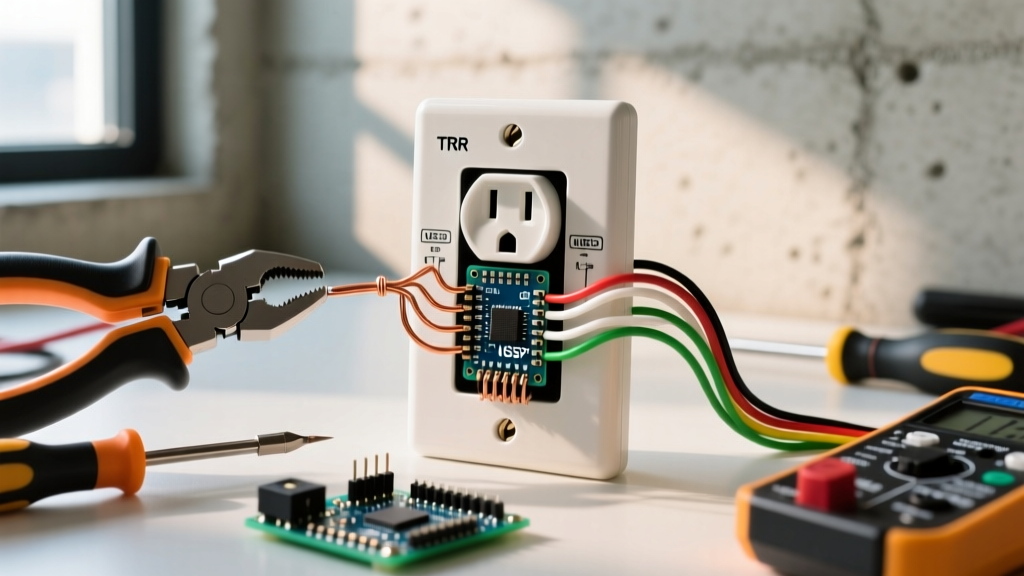
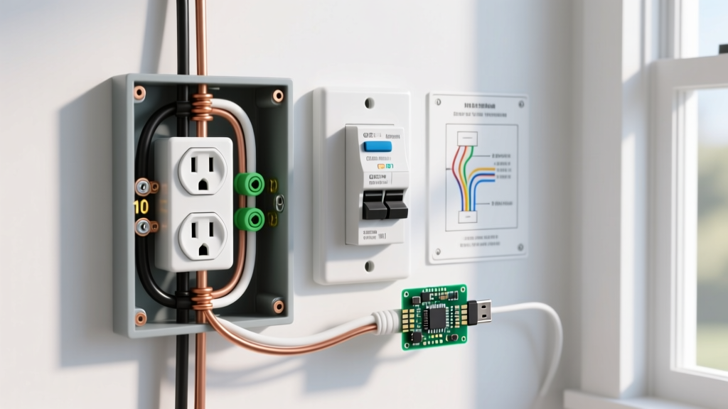
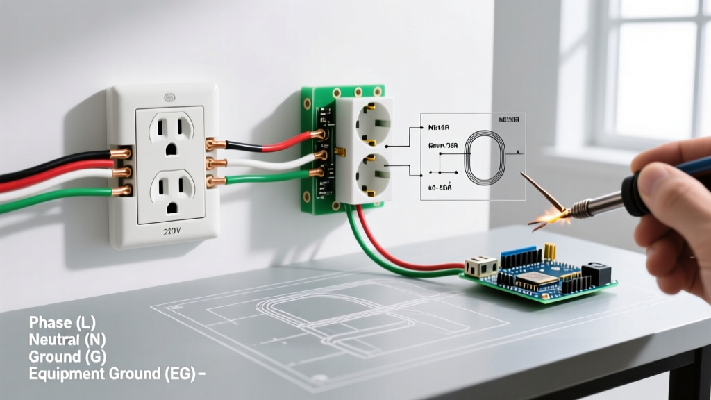
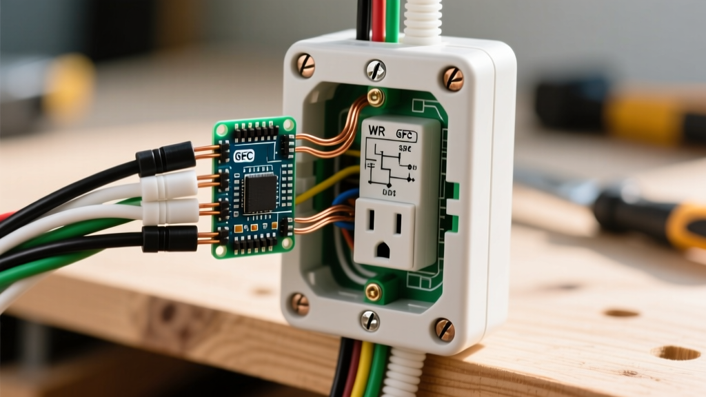
The most common configuration when changing an outdoor electrical outlet is replacing a standard duplex receptacle with a GFCI (Ground Fault Circuit Interrupter) or replacing an existing GFCI with a newer WR-rated model. Below is the terminal mapping reference for a single-location GFCI setup where no downstream outlets are protected.
| Wire Type | Color Code | GFCI Terminal | Termination Method |
|---|---|---|---|
| Hot (Line) | Black | Brass LINE Screw | Clockwise loop or straight insertion (back-wire) |
| Neutral | White | Silver LINE Screw | Clockwise loop or straight insertion (back-wire) |
| Equipment Ground | Bare / Green | Green Ground Screw | Clockwise loop under screw head |
Diagram Logic: Line vs. Load Terminals
A frequent failure point for DIYers changing outdoor electrical outlets is miswiring the LINE and LOAD terminals. The GFCI receptacle features two distinct sets of terminals:
- LINE Terminals: These receive the incoming power directly from the breaker panel. They are typically marked with yellow tape or the word 'LINE' on the back of the yoke.
- LOAD Terminals: These send GFCI-protected power to downstream receptacles. If you are only wiring a single outdoor outlet, the LOAD terminals must remain completely empty and covered by the included warning sticker.
Wiring Matrix: Feed-Through vs. Pigtail Protection
If your outdoor box contains multiple cables feeding other exterior outlets, you must choose a wiring topology. The table below compares the two acceptable methods for extending GFCI protection.
| Wiring Method | Diagram Configuration | Pros | Cons |
|---|---|---|---|
| Load Feed-Through | Incoming wires to LINE; Downstream wires to LOAD. | Uses fewer wire nuts; saves box space. | If the outdoor GFCI trips, all downstream outlets lose power. |
| Pigtail (Line-Only) | All hots and neutrals pigtailed together and connected ONLY to LINE. | Downstream outlets remain powered if the GFCI trips (if fed from a separate non-GFCI source, though outdoors this usually requires upstream GFCI). | Requires larger junction box volume (cubic inch calculations apply). |
Component Bill of Materials (BOM) & 2026 Pricing
To ensure longevity against UV radiation and thermal cycling, do not use indoor-rated components. Below is a professional-grade BOM for a standard 15A outdoor circuit upgrade.
| Component | Recommended Model | Specs | Est. Cost |
|---|---|---|---|
| GFCI Receptacle | Leviton 8125-W | 15A, 125V, WR, TR, Self-Test | $28.50 |
| In-Use Cover | Taymac MX1000B | Extra-Duty, Metal, 1-Gang | $19.00 |
| Weatherproof Box | Arlington 8100-1 | Non-Metallic, 22.5 cu in, 1-Gang | $14.75 |
| Cable Connector | Sigma 38051 | 3/8' NM Twin-Screw, Die-Cast | $1.20 |
Step-by-Step Termination & Torque Specifications
The U.S. Consumer Product Safety Commission (CPSC) notes that loose electrical connections are a primary cause of residential fires. When changing outdoor electrical outlets, mechanical torque is just as important as correct wiring.
- Strip the Wires: Use the built-in gauge on the side of the Leviton 8125-W. For 12 AWG solid copper, strip exactly 5/8 inch of insulation. Do not nick the copper conductor.
- Form the Loop: If using side-wiring (screw terminals), use needle-nose pliers to form a tight, clockwise hook. The loop should wrap around the screw shaft without overlapping the insulation or exposing bare wire outside the terminal washer.
- Apply Torque: Use an insulated torque screwdriver (e.g., Wiha 645P). Leviton specifies 14 in-lbs (1.6 N-m) for 12 AWG and 10 AWG wire, and 9 in-lbs for 14 AWG wire. Over-torquing can strip the brass threads; under-torquing leads to arcing.
- Ground Continuity: If using a non-metallic box (like the Arlington 8100-1), the bare ground wire connects only to the GFCI green screw. If using a metallic cast-aluminum box, you must pigtail the ground to both the GFCI and the box's internal green grounding screw.
Edge Cases & Troubleshooting Failure Modes
Even with perfect wiring, outdoor environments introduce unique failure modes. Use this diagnostic reference if the newly installed outlet fails to operate or trips immediately.
1. Nuisance Tripping on New GFCI
Symptom: The GFCI resets but trips within minutes, even with no load plugged in.
Root Cause: Moisture ingress in the conduit or upstream junction box, or a shared neutral with another circuit.
Resolution: Verify that the neutral (white) wire on the LOAD side is not shared with a non-GFCI circuit. GFCIs monitor the current differential between hot and neutral; a shared neutral will cause an immediate imbalance and trip the internal solenoid.
2. UV Degradation of Faceplates
Symptom: The plastic cover becomes brittle and cracks within 12 months.
Root Cause: Use of standard indoor nylon faceplates or cheap, non-UV-stabilized polycarbonate covers.
Resolution: Always verify the 'WR' stamp on the receptacle and use heavy-duty die-cast aluminum or UV-rated polycarbonate in-use covers (like the Taymac MX1000B).
3. Condensation Inside the In-Use Cover
Symptom: Water droplets form on the inside of the cover, leading to corrosion on the brass LINE terminals.
Root Cause: Lack of a weep hole and missing foam gasket seal.
Resolution: Ensure the foam gasket is compressed evenly against the siding. Drill a 1/8-inch weep hole at the absolute lowest point of the in-use cover frame to allow condensation and driven rain to escape. Apply a bead of clear 100% silicone caulk to the top and sides of the cover flange, leaving the bottom uncaulked to permit drainage.
Final Testing Protocol
After completing the physical installation and wiring, do not rely solely on the GFCI's internal 'TEST' button. The internal test button only verifies the electronic circuitry; it does not verify the integrity of the ground wire connection. Plug in a dedicated GFCI receptacle tester (e.g., Gardner Bender GRT-501). Press the black button on the tester. This forces a ground-fault current through the equipment grounding conductor, confirming that the outlet will safely trip and clear a fault in a real-world scenario.