
The Anatomy of a Standard 120V Duplex Receptacle
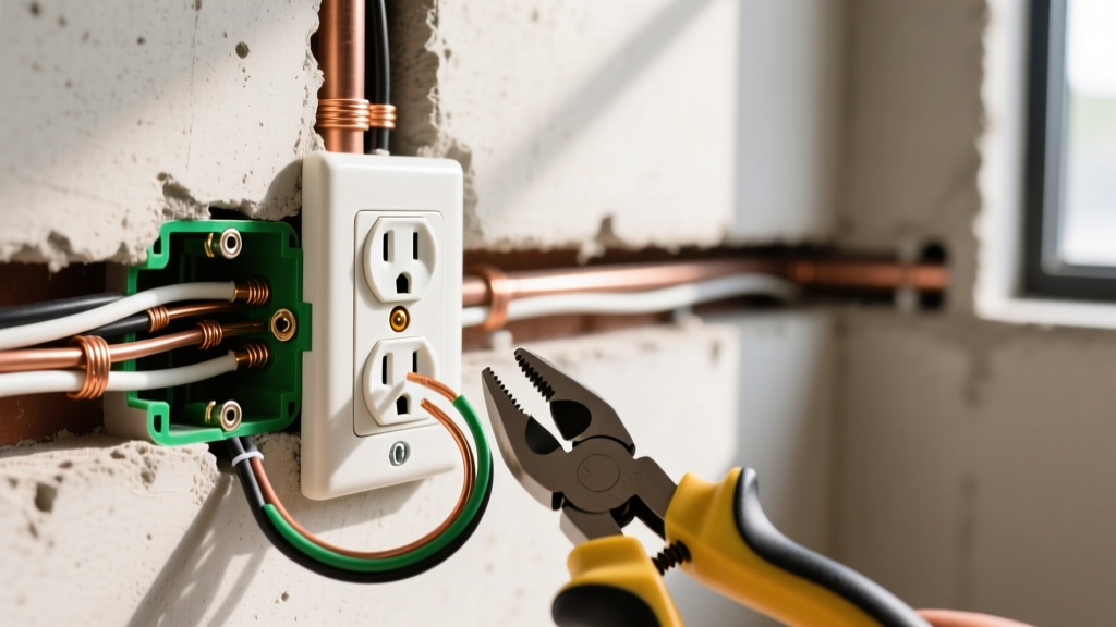
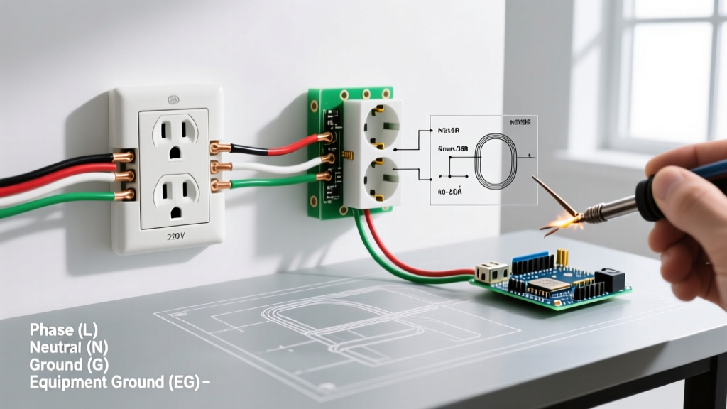
Understanding how to hook up electrical outlet devices safely requires a fundamental grasp of receptacle anatomy and National Electrical Code (NEC) compliance. A standard 15-amp or 20-amp 120V duplex receptacle features three primary terminal sets. The brass-colored screws are for the 'hot' conductor, the silver-colored screws are for the 'neutral' conductor, and the green screw is dedicated to the equipment grounding conductor. Modern installations mandate the use of Tamper-Resistant (TR) receptacles, such as the Leviton T5262 (15A) or Hubbell 5262-I (20A), which feature internal shutters to prevent foreign object insertion.
Terminal Mapping & Wire Color Reference
| Terminal Color | Function | Standard Wire Color | NEC Article Reference |
|---|---|---|---|
| Brass | Ungrounded (Hot) | Black or Red | Article 200.2 |
| Silver | Grounded (Neutral) | White or Gray | Article 200.2 |
| Green | Equipment Ground | Bare Copper or Green | Article 250.118 |
Connection Methods: Back-Stab vs. Side-Wire vs. Back-Wire Clamp
When learning how to hook up electrical outlet wiring, selecting the correct termination method is critical for long-term reliability and fire prevention.
- Push-In Back-Stab (Avoid): Found on cheap, builder-grade receptacles. These rely on a small internal spring clip that grips the wire. They are notorious for loosening over time due to thermal expansion and contraction, leading to high-resistance arcing faults.
- Side-Wire Screw (Acceptable): The wire is stripped, looped clockwise around the terminal screw, and tightened. This provides a solid mechanical connection but requires precise wire loop formation to prevent the screw from pushing the wire out.
- Back-Wire Clamp (Best Practice): Found on commercial and spec-grade receptacles (e.g., Leviton T5262). The straight-stripped wire is inserted into a rear hole, and tightening the screw lowers a heavy-duty brass clamp plate over the wire. This allows for faster installation and superior clamping force without the risk of strand fraying.
Step-by-Step Standard Outlet Wiring Procedure
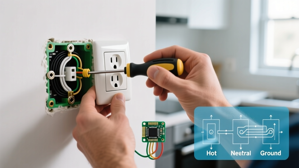
Follow this precise workflow to ensure your installation meets current safety standards and passes inspection.
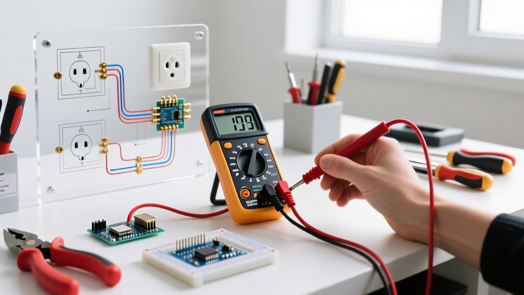
- De-energize and Verify: Turn off the branch circuit breaker. Use a non-contact voltage tester, followed by a digital multimeter like the Fluke T5-600, to confirm 0V between hot-to-neutral and hot-to-ground.
- Strip the Conductors: Using a precision wire stripper (e.g., Ideal 34-170), strip exactly 3/4 inch of insulation from the 14 AWG or 12 AWG solid copper conductors. Do not nick the copper, as this creates a stress fracture point.
- Terminate the Ground: Connect the bare copper ground wire to the green terminal screw. If connecting to a metal electrical box, use a grounding pigtail to bond the box and the receptacle simultaneously.
- Terminate the Neutral: Connect the white wire to one of the silver terminals. For side-wiring, ensure the loop goes clockwise so the screw pulls the loop tight.
- Terminate the Hot: Connect the black wire to one of the brass terminals.
- Apply Manufacturer Torque: Under NEC 110.14(D), terminals must be tightened to the manufacturer's specified torque. For most standard 15A/20A receptacles, this is 14 inch-pounds. Use a calibrated torque screwdriver like the Klein Tools 70907 to prevent under-tightening (arcing risk) or over-tightening (stripped threads).
Split-Wired (Half-Hot) Receptacle Diagram & Setup
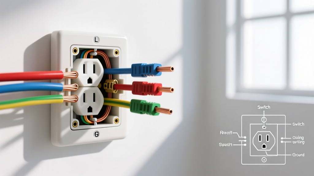
A split-wired outlet is commonly used in living rooms or bedrooms where one half of the receptacle is always hot, and the other half is controlled by a wall switch. This requires a 3-wire cable (Black, Red, White, Bare) running from the panel or switch box.
Wiring Configuration for Split Receptacles
- Break the Fin: Use needle-nose pliers to snap off the brass break-off fin connecting the top and bottom brass terminals. Do not remove the silver fin, as the neutral must remain shared.
- Top Brass Terminal: Connect the Black (always hot) wire.
- Bottom Brass Terminal: Connect the Red (switched hot) wire.
- Silver Terminal: Connect the White (neutral) wire.
- Green Terminal: Connect the Bare (ground) wire.
Code Warning: When wiring a split receptacle with a multi-wire branch circuit (MWBC), the two hot breakers must be tied together with a handle tie or be a single double-pole breaker to ensure simultaneous disconnect, per NEC 210.4(B).
GFCI Outlet Wiring: Line vs. Load Configuration
Ground Fault Circuit Interrupter (GFCI) receptacles protect against shock hazards in wet locations. Unlike standard outlets, GFCIs feature two distinct sets of terminals: LINE and LOAD.
Understanding LINE vs. LOAD
| Terminal Set | Function | Connection Source |
|---|---|---|
| LINE | Receives incoming power from the panel. | Main circuit hot and neutral. |
| LOAD | Sends protected power downstream. | Hot and neutral feeding additional standard outlets. |
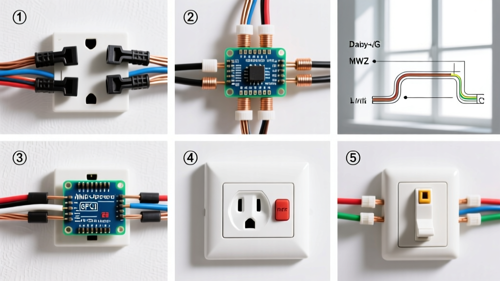
Common Failure Mode: If you connect the incoming power to the LOAD terminals, the GFCI will power up and function locally, but it will not provide ground-fault protection, and the internal test button will fail to trip the device. Always use a voltage tester to identify the incoming line wires before making connections.
Troubleshooting Matrix: Common Wiring Faults
Even experienced DIYers make mistakes when figuring out how to hook up electrical outlet circuits. Use this matrix to diagnose post-installation issues.
| Symptom | Probable Cause | Corrective Action |
|---|---|---|
| Receptacle tester shows 'Open Ground' | Ground wire not terminated or broken upstream. | Verify continuity from receptacle ground terminal to the panel ground bar. |
| Receptacle tester shows 'Hot/Neutral Reversed' | Black wire on silver screw; White wire on brass screw. | Swap the hot and neutral wires to their correct color-coded terminals. |
| Downstream outlets are dead, GFCI won't reset | Incoming power wired to LOAD terminals instead of LINE. | Move incoming power wires to the LINE terminals. |
| Breaker trips immediately upon plugging in a load | Hot-to-ground short or pinched wire insulation in the box. | Inspect for bare copper touching the metal box or ground screw. |
Authoritative References & Code Citations
Electrical wiring must always comply with local and national codes. The guidelines presented in this wiring diagram reference are based on the following authoritative standards:
- NFPA 70: National Electrical Code (NEC) - The benchmark for safe electrical design, installation, and inspection to protect people and property from electrical hazards.
- OSHA Electrical Safety Standards - Occupational Safety and Health Administration guidelines for workplace and residential electrical safety practices.
- U.S. Department of Energy: Electrical Wiring - Federal guidelines and energy efficiency considerations for residential electrical systems and receptacle loads.