
Diagnosing Faults in Switch and Receptacle Combination Devices
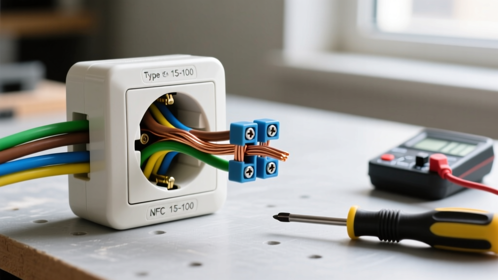
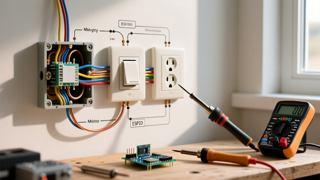
Combination devices, which pair a single-pole toggle or rocker switch with a standard 15A or 20A duplex receptacle in a single-gang footprint, are incredibly common in residential wiring. They are frequently found in bathrooms, kitchens, and garages where space is limited but both a switched light and an unswitched power source are required. However, when these devices fail, the internal wiring complexity often leads to confusion. To accurately diagnose a malfunctioning unit, you must deeply understand the wiring diagram for light switch and outlet combo devices and how to map those schematics to real-world multimeter testing.
In 2026, standard 15A combination devices like the Leviton 5243 (toggle) or Eaton 7294W (rocker) typically retail between $8.50 and $14.00. Higher-end Decora-style smart combos or AFCI/GFCI protected combos can range from $35.00 to $65.00. Before replacing a seemingly dead unit, a systematic diagnostic approach using the device's internal wiring logic will save you time and prevent dangerous miswiring.
Anatomy of the Combo Device Wiring Diagram
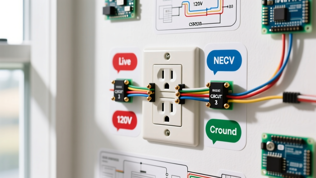
Unlike a standard duplex outlet where both receptacles share the same hot feed, a combo device separates the switch mechanism from the receptacle mechanism internally. When reviewing the manufacturer's wiring diagram for light switch and outlet combo units, you will identify four primary connection points:
- LINE Terminal (Brass Screw): The incoming always-hot power source from the breaker panel.
- LOAD Terminal (Brass Screw): The outgoing switched hot wire leading to the light fixture.
- NEUTRAL Terminal (Silver Screw): The return path completing the circuit for both the receptacle and the light fixture.
- GROUND Terminal (Green Screw): The bare copper or green insulated safety ground.
The Critical Break-Off Fin
The most misunderstood component in the wiring diagram for light switch and outlet combo setups is the brass break-off fin (or tab) located on the hot side of the receptacle. This fin dictates the behavior of the outlet:
- Fin Intact: The receptacle is controlled by the switch. Power flows from the switch's internal mechanism to the receptacle's hot terminal. This is used when you want the switch to turn on a lamp plugged into the outlet.
- Fin Removed: The receptacle is 'always hot.' The LINE hot wire must be pigtailed to both the switch's LINE terminal and the receptacle's hot terminal. This is the standard configuration for bathroom vanity lights (switched) and hair dryer outlets (always hot).
Expert Warning: According to the Consumer Product Safety Commission (CPSC), improper handling of the break-off tab or confusing LINE and LOAD terminals is a leading cause of localized electrical fires and shock hazards in DIY combo-device installations. Always verify the fin's status before energizing the circuit.
Step-by-Step Multimeter Diagnostic Flow
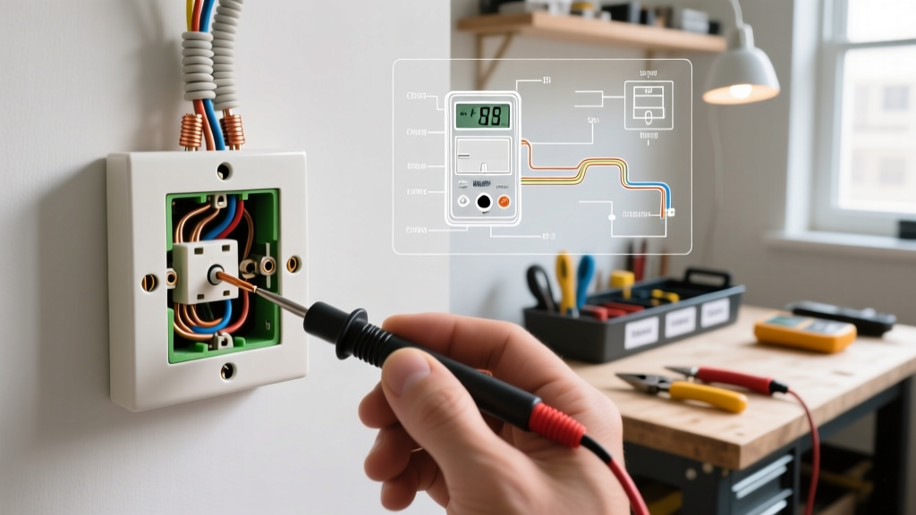
When a combo device fails, do not immediately rip it out of the wall. Use a True-RMS digital multimeter (such as the Fluke 117 or Klein Tools MM600) to trace the fault against the wiring diagram.
Step 1: Verify Incoming Power (LINE Check)
Set your multimeter to AC Voltage (V~). With the breaker ON and the switch OFF, place the black probe on the bare ground wire and the red probe on the LINE brass screw. You should read between 118V and 124V. If you read 0V, the fault is upstream (tripped breaker, loose wire nut in the junction box, or a backstabbed connection that has failed).
Step 2: Test the Switch Mechanism (LOAD Check)
Keep the black probe on the ground. Move the red probe to the LOAD brass screw (the wire going to the light). Toggle the switch. The voltage should jump from 0V to 120V when switched ON. If the switch toggles but no voltage appears at the LOAD screw, the internal switch contacts have failed, requiring a full device replacement.
Step 3: Test the Receptacle
Use a standard receptacle tester or your multimeter probes inserted into the hot and neutral slots. If the switch works but the outlet is dead, check the brass break-off fin. If the fin was removed to make the outlet always hot, verify that the incoming hot wire is properly pigtailed to both the switch LINE and the receptacle hot terminal. A common failure mode is a loose wire nut on this pigtail inside the crowded single-gang box.
Combo Device Failure Mode Matrix
Use this diagnostic matrix to quickly cross-reference your symptoms with the wiring diagram for light switch and outlet combo configurations.
| Observed Symptom | Wiring Diagram Check | Probable Root Cause & Resolution |
|---|---|---|
| Light works, but outlet is completely dead. | Check receptacle hot terminal and break-off fin status. | Fin was removed for 'always hot' but the hot feed was not pigtailed to the receptacle terminal. Add a 12 AWG or 14 AWG pigtail. |
| Outlet only works when the light switch is turned ON. | Check brass break-off fin on the hot side. | Fin is intact, wiring the outlet in series with the switch. Break the fin off with needle-nose pliers and pigtail the hot feed. |
| Light flickers or buzzes; outlet works fine. | Check LOAD terminal torque and wire strip length. | Loose connection on the LOAD screw or wire insulation is caught under the screw head. Re-strip wire to 5/8 inch and torque to manufacturer specs. |
| Both light and outlet are dead; breaker is ON. | Check LINE terminal and upstream pigtails. | Failed backstabbed (push-in) connection on a previous device upstream, or a broken hot wire in the wall cavity. Trace voltage back to the panel. |
| GFCI/AFCI combo trips immediately upon plugging in a load. | Check Neutral (silver) terminal and shared neutral paths. | Neutral from the light fixture is improperly tied to a different circuit's neutral. Light and outlet must share the exact same neutral. |
Advanced Edge Cases and Code Compliance
The Backstabbing Epidemic
Many older combination devices feature push-in 'backstab' connectors on the rear. While UL-listed, these spring-loaded contacts are notorious for loosening over time due to thermal expansion and contraction, especially under heavy loads like space heaters or hair dryers. When troubleshooting a dead outlet on a combo device, always inspect the backstab connections. Best practice in 2026 is to exclusively use the side screw terminals or screw-clamp plates, torqued to roughly 12-14 inch-pounds for 14 AWG wire.
Box Fill Calculations (NEC Article 314)
When upgrading to modern smart combo devices or GFCI-protected combo units, the physical depth of the device increases significantly. Standard 15A combo switches are roughly 1.1 inches deep, while GFCI combos can exceed 1.4 inches. According to the National Fire Protection Association (NFPA) NEC guidelines, you must calculate box fill to prevent wire crushing. A single-gang box must have a minimum volume of 18 cubic inches for a standard combo device with 14/2 NM-B cable. If your box is undersized, you must install a box extender ring to maintain safe heat dissipation and prevent insulation damage.
Shared Neutral Violations
In older multi-wire branch circuits (MWBC), electricians sometimes shared a single neutral wire between two different hot phases. If you are installing a GFCI combo device, the internal electronics will detect the imbalanced current returning on a shared neutral and trip immediately. The Occupational Safety and Health Administration (OSHA) and NEC strictly require that GFCI and AFCI devices have a dedicated, isolated neutral for their specific circuit. If your diagnostic multimeter testing shows 0V between hot and neutral, but 120V between hot and ground, you likely have an open neutral or a shared neutral violation that must be corrected in the panel.
Final Troubleshooting Takeaways
Mastering the wiring diagram for light switch and outlet combo devices requires moving beyond simple color-matching. You must understand the internal routing of current, the physical state of the break-off fin, and the strict requirements for shared neutrals and box fill. By utilizing a True-RMS multimeter to verify LINE, LOAD, and NEUTRAL continuity step-by-step, you can accurately diagnose whether the fault lies in a failed internal mechanism, a loose pigtail, or an upstream code violation. Always prioritize side-wiring over backstabbing, and ensure your single-gang boxes meet the 2026 NEC volume requirements for modern, deeper combination devices.