
The "Electrical Outlet Positive" Misconception
If you are transitioning from low-voltage electronics, automotive work, or solar DC setups into standard residential wiring, you might find yourself searching for the electrical outlet positive wire. Here is the most critical concept to grasp before you touch a single screwdriver: standard North American residential wall outlets do not have a positive or negative terminal.
Terms like "positive" and "negative" apply strictly to Direct Current (DC) systems, where electrons flow continuously in one direction from the positive terminal to the negative terminal. However, your home's electrical panel delivers Alternating Current (AC). In a standard US 120V AC circuit operating at 60Hz, the current literally reverses direction 120 times per second. Because the flow is constantly alternating, there is no permanent "positive" pole.
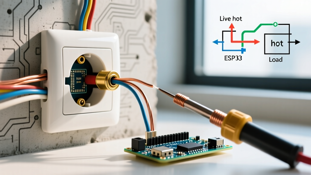
Instead of positive and negative, AC receptacle wiring utilizes three distinct conductors: Hot (Line), Neutral, and Ground. When beginners ask about the "electrical outlet positive," they are almost always referring to the Hot wire, which carries the alternating voltage from the breaker panel to the device.
Translating DC Terminology to AC Receptacle Wiring
To prevent catastrophic wiring errors, you must mentally map your DC knowledge to AC standards. The National Electrical Code (NEC), maintained by the National Fire Protection Association (NFPA), strictly defines these roles and their corresponding insulation colors.
| System Type | Terminal / Role | Standard Wire Color | Receptacle Screw Color | Voltage Potential |
|---|---|---|---|---|
| DC (Direct Current) | Positive (+) | Red | N/A | Constant (+V) |
| DC (Direct Current) | Negative (-) | Black | N/A | 0V (Reference) |
| AC (Alternating Current) | Hot / Line (The "Positive" Equivalent) | Black (or Red/Blue) | Brass / Gold | 120V AC (Alternating) |
| AC (Alternating Current) | Neutral (The Return Path) | White (or Grey) | Silver | ~0V AC (Under load) |
| AC (Alternating Current) | Ground (Safety Earth) | Bare Copper or Green | Green | 0V (Fault path only) |
Essential Tools for Identifying the Hot Wire Safely
Never assume wire colors are correct. Previous DIYers may have swapped wires, or a switch loop might use a white wire as a hot conductor. According to OSHA electrical safety guidelines, verifying the absence of voltage is mandatory before contact. For a beginner installation tutorial, you need two specific tools:
- Non-Contact Voltage Tester (NCVT): A tool like the Klein Tools NCVT-2 (approx. $25) detects the electromagnetic field around the Hot wire without requiring bare metal contact. It is your first line of defense.
- Digital Multimeter (DMM): An NCVT can yield false positives due to phantom voltage. A true RMS multimeter like the Fluke 117 (approx. $220) or a budget AstroAI DM6000AR (approx. $35) is required to verify exact 120V potential between Hot and Ground.
Step-by-Step Installation: Wiring the "Positive" (Hot) Terminal
When replacing or installing a standard 15-Amp duplex receptacle (such as the highly reliable Leviton R52-05320-00W, which costs around $2.50), follow this exact sequence to ensure the Hot wire is terminated correctly.
Phase 1: Isolation and Verification
- Kill the Power: Turn off the corresponding 15A or 20A breaker at the main panel. Apply a physical lockout/tagout device if others are in the home.
- Test for Dead: Insert your NCVT into the top and bottom slots of the existing outlet. The Hot slot (the shorter vertical slot) should yield no beep or red light.
- Multimeter Verification: Set your DMM to V~ (AC Voltage). Place the black probe on the Ground screw and the red probe into the Hot slot. The reading must be 0.0V.
Phase 2: Preparation and Termination
- Strip the Wires: Use wire strippers to remove exactly 3/4-inch of insulation from the 14 AWG (for 15A circuits) or 12 AWG (for 20A circuits) solid copper wires.
- Form the J-Hook: Using needle-nose pliers, bend the exposed copper into a clockwise "J" hook. The clockwise direction is vital; as you tighten the terminal screw, the loop will close tightly around the shaft rather than being pushed outward.
- Terminate the Hot (The "Positive"): Hook the Black wire around the Brass terminal screw. Tighten firmly to roughly 12 in-lbs. Ensure no bare copper is exposed outside the terminal plate.
- Terminate the Neutral: Hook the White wire around the Silver terminal screw.
- Terminate the Ground: Hook the Bare/Green wire around the Green terminal screw at the bottom of the yoke.
CRITICAL SAFETY WARNING: Never use the "backstab" or push-in quick-wire holes on the back of a receptacle for the Hot or Neutral wires. While permitted by UL for 14 AWG wire, spring-loaded push-in terminals have a vastly higher failure rate over time due to thermal expansion and arcing. Always use the side screw terminals for a permanent mechanical and electrical bond.
Critical Failure Modes and Edge Cases
Understanding what happens when the "electrical outlet positive" (Hot) is wired incorrectly is crucial for troubleshooting.
Reverse Polarity (Hot and Neutral Swapped)
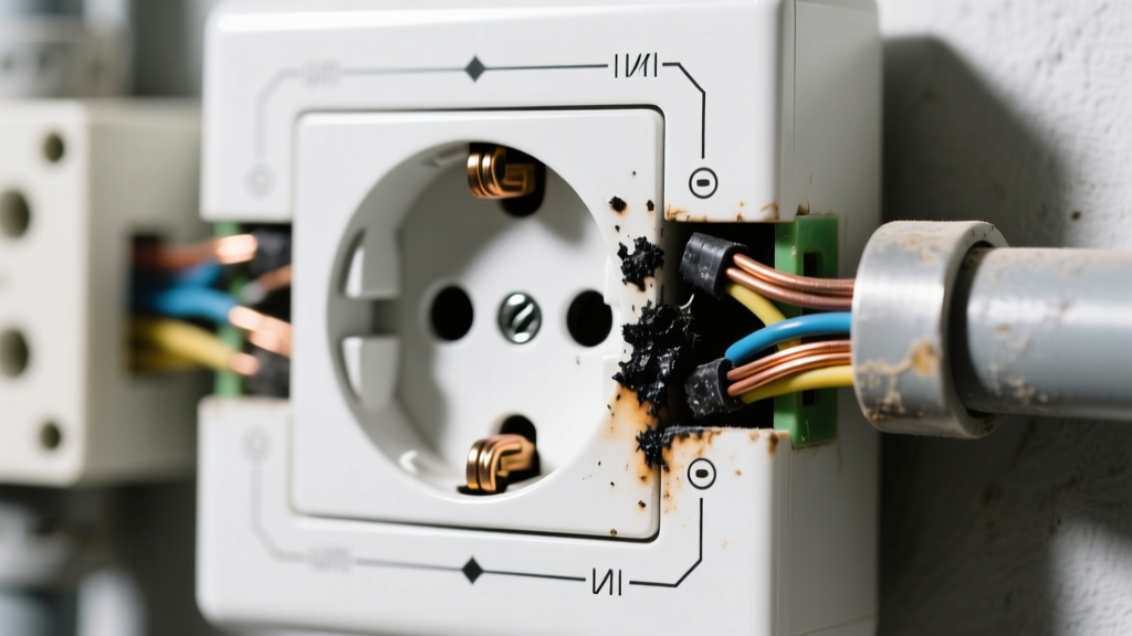
If you connect the Black (Hot) wire to the Silver screw and the White (Neutral) wire to the Brass screw, the outlet will still power a lamp or TV. However, you have created a severe shock hazard. In a properly wired outlet, the internal switch of an appliance breaks the Hot leg. If reversed, the appliance's internal components remain energized at 120V even when turned "off." Always verify correct polarity using a $10 receptacle tester (like the Gardner Bender GRT-500) after installation.
Open Ground
Connecting the Hot and Neutral but skipping the Ground screw leaves the user unprotected from internal appliance faults. If a live wire inside a metal toaster touches the casing, the casing becomes energized at 120V. The Ground wire provides a low-resistance path back to the panel, tripping the breaker instantly.
2026 NEC Code Compliance for Standard Receptacles
As of the 2026 National Electrical Code cycle, simply knowing which wire is Hot is not enough; the physical receptacle you install must meet modern safety mandates. The Electrical Safety Foundation International (ESFI) heavily advocates for these life-saving updates:
- Tamper-Resistant (TR) Receptacles: All 15A and 20A, 125V and 250V non-locking receptacles in residential dwellings must be TR. These feature internal spring-loaded shutters that only open when equal pressure is applied to both the Hot and Neutral slots simultaneously, preventing children from inserting single metal objects.
- AFCI / GFCI Protection: Depending on the room, your Hot wire may need to originate from an Arc-Fault Circuit Interrupter (AFCI) breaker (required in bedrooms, living rooms) or a Ground-Fault Circuit Interrupter (GFCI) receptacle/breaker (required in kitchens, bathrooms, garages, and outdoors).
Frequently Asked Questions (FAQ)
Can I wire a standard outlet if my house has no ground wire?
If you are replacing an existing ungrounded (2-prong) receptacle in an older home, the NEC allows you to install a 3-prong GFCI receptacle. You must connect the Hot to the Brass screw and Neutral to the Silver screw, leaving the Ground screw empty. You must apply the included "No Equipment Ground" sticker to the faceplate. The GFCI will protect against shock, even without a physical ground wire.
Why are there two sets of Brass and Silver screws on the outlet?
Standard duplex receptacles have a top half and a bottom half. By default, a small brass tab connecting the two Hot (Brass) screws and a silver tab connecting the two Neutral (Silver) screws allow power to flow to both halves. If you want to control the top half with a wall switch while keeping the bottom half always hot (a "split-wired" receptacle), you must snap off the brass tab using pliers. Never break the silver tab unless you are feeding two completely separate 240V split-phase circuits, which is rare in modern residential wiring.
Is the wider slot on the outlet the positive?
No. The wider vertical slot is the Neutral. The shorter vertical slot is the Hot (the AC equivalent of the "positive" supply). This physical design ensures that polarized plugs (where one blade is wider) can only be inserted one way, guaranteeing that the appliance's internal fuse and switch are always placed on the Hot leg.