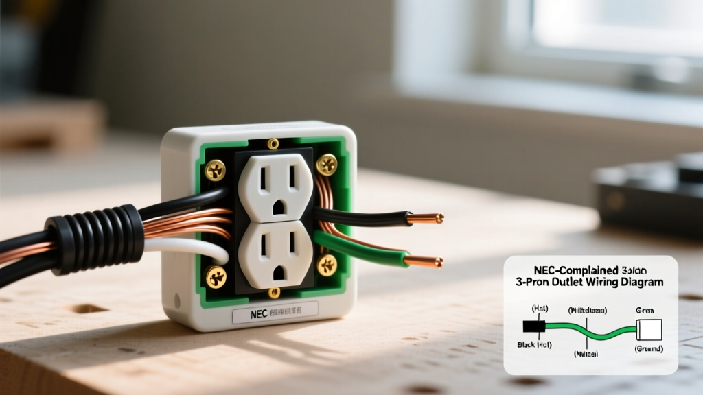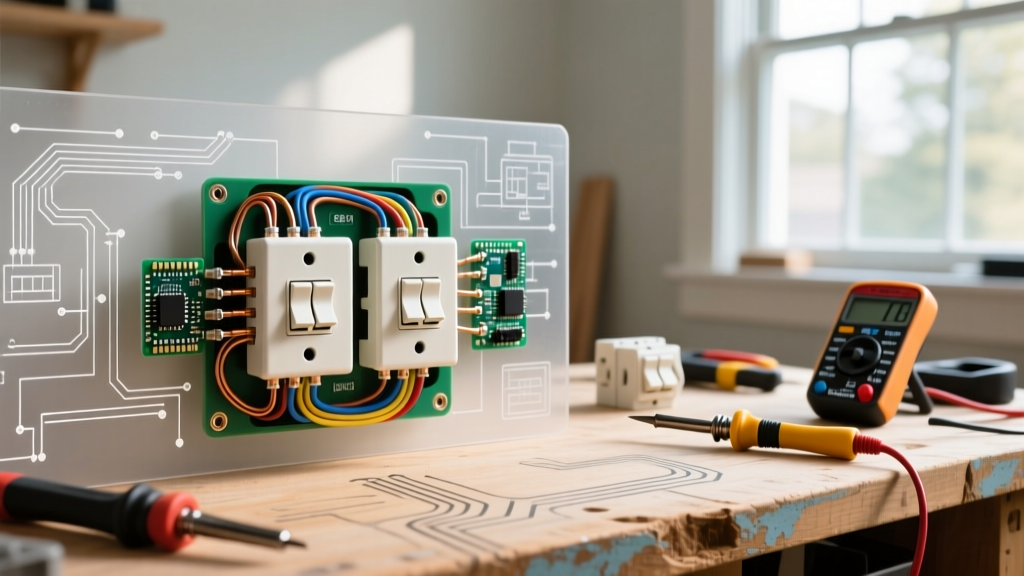

Defining the 'Double Switch' in Modern Residential Wiring
When homeowners and DIYers search for solutions to double switch electrical wiring problems, confusion often stems from terminology. In the electrical trade, a 'double switch' typically refers to one of two entirely different devices. Understanding which device you are troubleshooting is the critical first step in diagnosing your circuit failure.
- Duplex Switch (Twin Switch): A single-gang device featuring two separate toggles or rockers on one yoke (e.g., Leviton Decora 5641-W or Eaton 1877W, typically priced around $4.50 to $6.00). It controls two separate 120V loads, such as a ceiling fan and a light fixture, using a shared line (hot) feed and two separate load wires.
- Double-Pole Switch: A single-toggle device (e.g., Leviton 3032-PL, approx. $8.50) designed to break two hot legs simultaneously. It is strictly used for 240V appliances like baseboard heaters, water heaters, or heavy-duty workshop equipment.
Troubleshooting double switch electrical wiring requires a systematic approach, moving from the breaker panel to the terminal screws. Below is a comprehensive diagnostic framework for both configurations, updated for the 2026 National Electrical Code (NEC) landscape.
Essential Diagnostic Toolkit
Before removing any wall plates, ensure you have the proper testing equipment. Guessing with wire nuts leads to short circuits and arc faults.
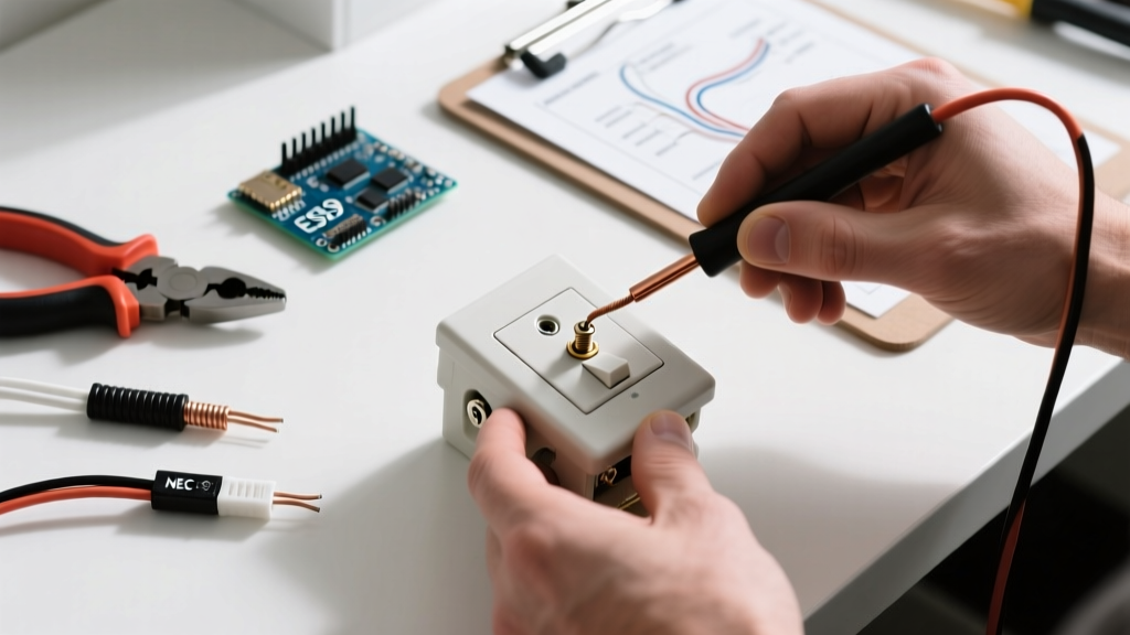
- Non-Contact Voltage Tester (NCVT): A reliable dual-range tester like the Klein Tools NCVT-2 ($25) to verify the absence of voltage before touching bare copper.
- Digital Multimeter (DMM): Essential for continuity and voltage drop testing. A True-RMS meter like the Fluke 117 ($180) or a budget-friendly AstroAI DM6000AR ($40) will accurately read ghost voltages on long wire runs.
- Torque Screwdriver: The 2026 NEC strictly enforces terminal torque specifications. A standard 14 AWG or 12 AWG copper wire requires approximately 14 in-lbs of torque on standard switch terminals to prevent thermal creep and arcing.
Troubleshooting Duplex (Twin) Switches (120V Circuits)
Duplex switches are notorious for specific installation errors. Here is how to diagnose the most common failure modes.
Symptom 1: Neither Toggle Responds
If both switches on the duplex yoke are dead, the issue is upstream of the device.
- Diagnostic Step: Turn off the breaker, remove the switch, and separate all wires. Turn the breaker back on and use your NCVT to identify the line (hot) wire. If no wire registers as hot, the fault lies in a tripped breaker, a failed GFCI upstream, or a severed wire inside the wall cavity.
- Edge Case: If the line wire is hot, but the switch fails to pass power to the load wires when toggled, the internal brass contacts have likely fused open due to previous overloading or arc damage. Replace the switch immediately.
Symptom 2: One Toggle Works, The Other is Dead
This is the most frequent complaint with double switch electrical wiring in older homes. The root cause is almost always a mismanaged break-off fin or a failed push-in (backstab) connection.
The 'Broken Fin' Mistake: On a standard duplex switch, the brass (hot) side features a small metal fin connecting the two line terminals. If your wall box only has ONE hot feed wire (which is then pigtailed to both terminals, or daisy-chained), that fin MUST remain intact. If a previous DIYer broke the fin off thinking it was required for all installations, the second switch will receive no power. Conversely, if you have TWO separate hot feeds from different breakers, the fin MUST be removed to prevent a 240V dead short.
Symptom 3: Switch Trips GFCI or Breaker Immediately
If toggling the switch causes an immediate trip, you likely have a shared neutral violation or a crossed load wire.
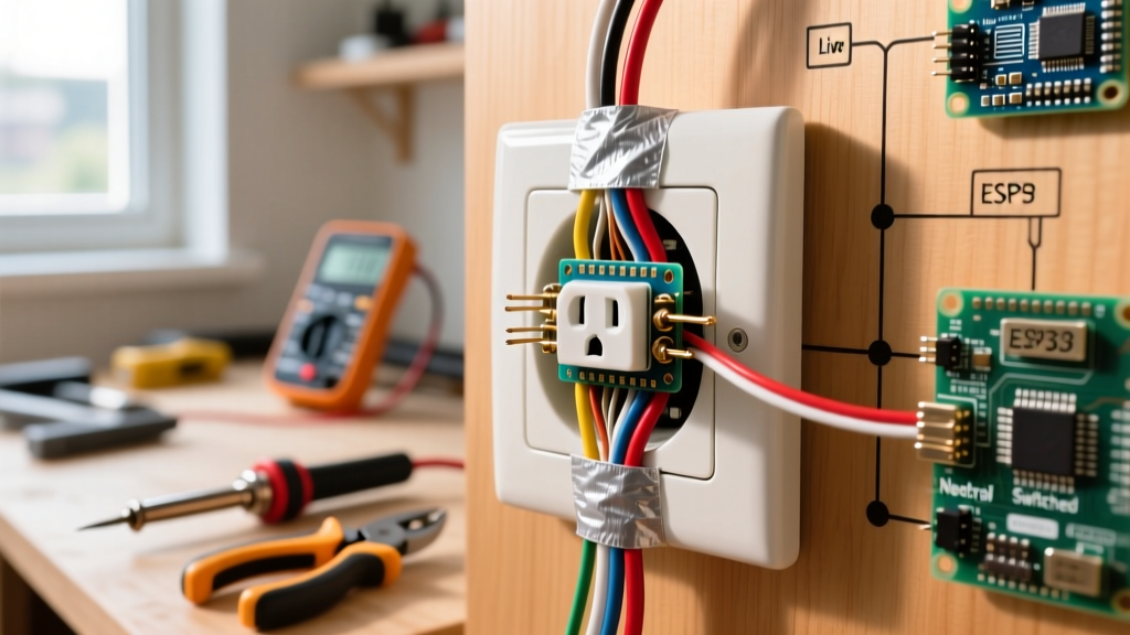
- Shared Neutral Hazard: If the two loads (e.g., fan and light) are on different circuits but share a single neutral wire, toggling one switch can cause neutral overload or GFCI tripping. The NEC requires a dedicated neutral for each circuit or a 2-pole handle tie (NEC 210.4).
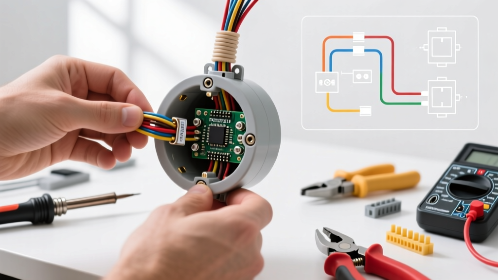
- Backstab Failure: Push-in (backstab) terminals rely on a tiny internal spring. Over years of thermal cycling (heating and cooling under load), the spring loses tension, causing micro-arcing. This creates carbon buildup, eventually leading to a dead circuit or a melted switch housing. Always use the side-wire terminal screws with a proper shepherd hook bend.
Diagnosing Double-Pole Switches (240V Circuits)
Double-pole switches handle high-current 240V loads. Troubleshooting these requires extreme caution, as a shock from a 240V line can be fatal.
Symptom: The 240V Appliance Will Not Turn On
Do not immediately assume the switch is faulty. 240V circuits rely on two 120V legs (L1 and L2) originating from a double-pole breaker.
- Test the Breaker: With the switch OFF, use your multimeter (set to AC Voltage) to test across the two line wires entering the switch box. You should read between 235V and 245V. If you read 0V, the issue is at the panel. If you read 120V, one leg of the double-pole breaker has tripped or failed.
- Test the Switch Continuity: Turn the breaker OFF and lock it out. Set your multimeter to Continuity (the diode/beep setting). Place one probe on the L1 line terminal and the other on the L1 load terminal. Toggle the switch. It should beep when ON, and show 'OL' (Open Line) when OFF. Repeat for L2. If one pole fails the continuity test while the other passes, the internal mechanical linkage is broken. The switch must be replaced.
Diagnostic Matrix: Multimeter Readings & Solutions
Use this quick-reference table to map your multimeter findings to actionable solutions.
| Multimeter Reading (Switch ON) | Test Points | Probable Fault | Actionable Solution |
|---|---|---|---|
| 0V AC | Line to Ground | Lost upstream power / Tripped breaker | Check panel, reset GFCI, verify wire nuts in upstream junction boxes. |
| 120V AC | Line to Ground, but 0V on Load to Ground | Failed internal switch contact or loose backstab | Replace switch; side-wire new device using 14 in-lbs torque. |
| 120V AC | Load to Ground (but fixture remains off) | Open neutral at the fixture or broken load wire | Inspect fixture canopy wire nuts; check for severed cable in attic/crawlspace. |
| 240V AC | L1 Line to L2 Line (Double-Pole Switch) | Normal upstream power | Proceed to continuity test across switch poles with power OFF. |
Code Compliance & Safety Warnings
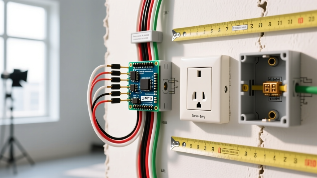
When repairing or replacing double switch electrical wiring, adherence to the latest safety standards is non-negotiable. According to NFPA NEC guidelines, all switch connections must be made within an approved enclosure (box), and the box must be large enough to prevent wire crowding. For a standard duplex switch with two 14/3 cables, you need a minimum box volume of 18 cubic inches to safely accommodate the conductors, pigtails, and the device yoke.
Furthermore, if your duplex switch is fed by a Multi-Wire Branch Circuit (MWBC) where the two hot wires share a single neutral, NEC Article 210.4(B) mandates a simultaneous disconnect. This means you cannot use a standard duplex switch with an intact fin; you must use a double-pole switch or install a recognized handle-tie on two adjacent single-pole breakers to ensure both legs are killed during maintenance. For comprehensive home electrical safety practices and hazard prevention, refer to the CPSC Electrical Safety Education Center.
Final Diagnostic Advice
Ninety percent of double switch wiring faults are not caused by the switch itself, but by poor termination practices—specifically, the use of backstab terminals, under-torqued screws, or improperly stripped wire insulation pushing against the terminal plate. When you open the wall box to diagnose the fault, take the extra five minutes to strip the wires cleanly to exactly 3/4 inch, form tight shepherd hooks, and torque the terminal screws to the manufacturer's specification. This ensures a low-resistance connection that will safely carry the load for decades without thermal degradation.