
The Critical Role of Shore Power Inspection in RV Electrical Safety
Connecting a modern recreational vehicle to a shore power pedestal is not as simple as plugging in a household appliance. As of 2026, modern RVs feature sophisticated inverter/chargers, residential refrigerators, and dual AC units that draw massive continuous current. A miswired receptacle at an RV park or a private residence can instantly destroy a $3,500 onboard power management system or, worse, create a lethal shock hazard on the RV chassis.
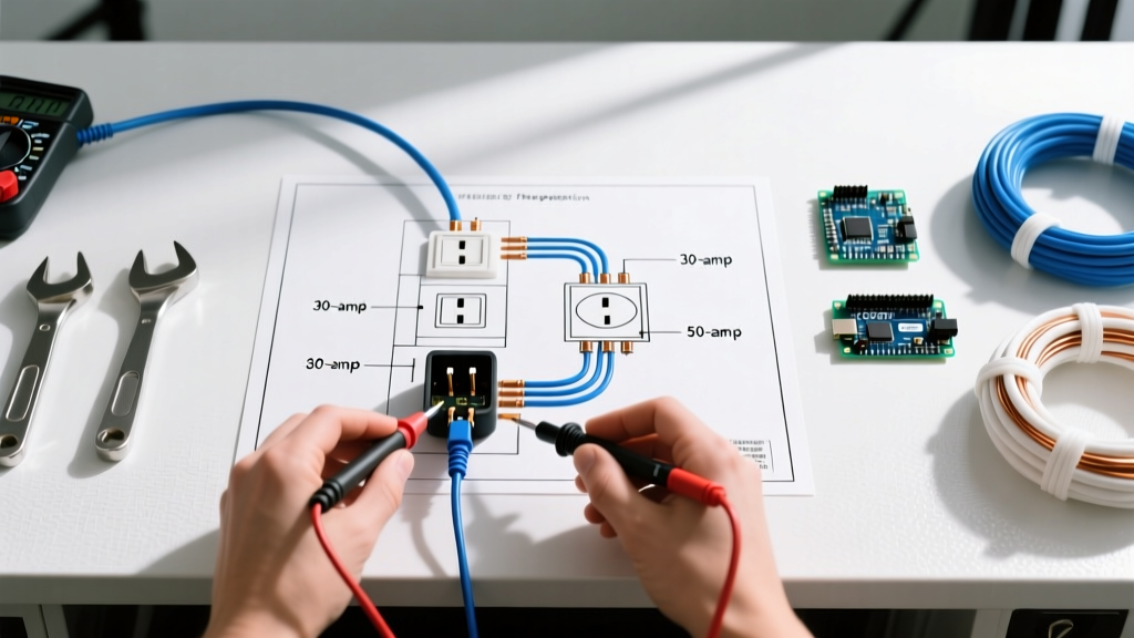
Consulting a precise wiring diagram for RV plug setups is the mandatory first step for any electrician, RV technician, or advanced DIYer inspecting a shore power connection. Unlike standard residential outlets, RV receptacles operate under specific National Electrical Code (NEC) Article 551 guidelines, which dictate strict grounding and polarity rules. This inspection and testing guide will walk you through verifying 30-amp and 50-amp RV receptacles using professional diagnostic protocols.
Decoding the Wiring Diagram for RV Plug Configurations
Before applying power or opening a receptacle cover, you must understand the two primary RV shore power standards. The most common mistake made by amateur electricians is confusing a NEMA 10-30 (dryer outlet) or NEMA 14-50 (electric range) with an RV-specific receptacle. RVs exclusively use the NEMA TT-30 for 30-amp service and the NEMA 14-50 for 50-amp service.
NEMA TT-30R (120V, 30-Amp)
The TT-30 is a 120-volt only, 3-wire configuration. It looks similar to a NEMA 10-30 but features a distinct angled neutral slot to prevent cross-plugging. According to the RV Industry Association (RVIA), the TT-30 must be protected by a 30-amp breaker and wired with a minimum of 10 AWG copper wire.
NEMA 14-50R (120/240V, 50-Amp)
The 14-50 is a 4-wire configuration providing two 120V legs (out of phase), a neutral, and a ground. While the pedestal supplies 240V between the two hot legs, the RV internal system only utilizes the two 120V legs to neutral. This requires a 50-amp double-pole breaker and a minimum of 6 AWG copper wire (4 AWG is strongly recommended for runs exceeding 50 feet to mitigate voltage drop).
Pinout and Terminal Reference Matrix
| Receptacle Type | Terminal ID | Function | NEC Wire Color | Voltage to Ground |
|---|---|---|---|---|
| TT-30 (30A) | X (Brass) | Hot (Line) | Black | 120V |
| TT-30 (30A) | W (Silver) | Neutral | White | 0V (Ideal) |
| TT-30 (30A) | G (Green) | Equipment Ground | Green/Bare | 0V |
| 14-50 (50A) | X (Brass) | Hot Leg 1 | Black | 120V |
| 14-50 (50A) | Y (Brass) | Hot Leg 2 | Red | 120V |
| 14-50 (50A) | W (Silver) | Neutral | White | 0V (Ideal) |
| 14-50 (50A) | G (Green) | Equipment Ground | Green/Bare | 0V |
Phase 1: Pre-Power Visual and Mechanical Inspection
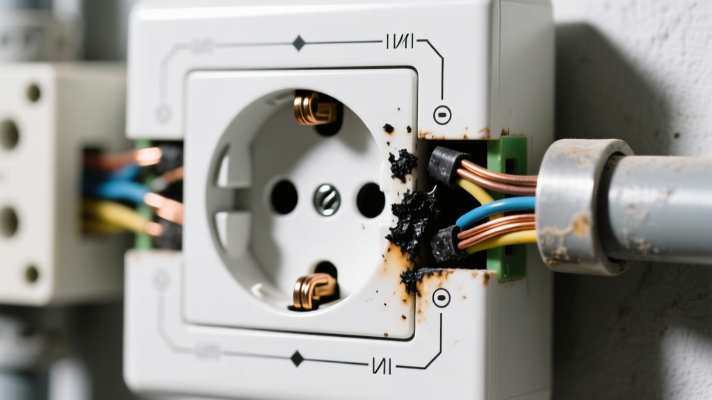
Never skip the de-energized physical inspection. Thermal cycling from high-amperage RV loads causes improperly terminated wires to loosen over time, leading to arcing and melted receptacles.
- Verify Breaker Sizing: Confirm the TT-30 is on a single-pole 30A breaker and the 14-50 is on a double-pole 50A breaker. A 14-50 on a 40A breaker will cause nuisance tripping under heavy RV loads.
- Inspect Wire Gauge and Stripping: Ensure no bare copper is exposed outside the terminal (a shock hazard) and no insulation is trapped inside the terminal clamp (causing high resistance).
- Check for Strand Creep: On stranded wire, ensure no loose copper strands are bridging the gap between the Hot and Ground terminals.
- Apply Correct Torque: This is the most frequently ignored step. Use a calibrated torque screwdriver. For a Leviton or Eaton TT-30 receptacle with 10 AWG wire, torque the terminal screws to 14 to 18 in-lbs. For a 14-50 receptacle with 6 AWG wire, torque to 35 to 40 in-lbs. Under-torquing guarantees eventual thermal failure.
Phase 2: Live Voltage and Polarity Testing Protocol
Once the physical inspection is complete and the cover plate is temporarily secured, restore power at the breaker. Use a True-RMS digital multimeter (such as the Fluke 117, priced around $190) for accurate readings, as cheap analog testers will not detect high-resistance ghost voltages.
Step-by-Step Multimeter Testing
- Hot to Neutral (X to W): Should read between 110V and 125V. If it reads significantly lower (e.g., 104V), you have severe voltage drop upstream or an undersized feeder wire.
- Hot to Ground (X to G): Should read identically to Hot to Neutral (within 1V).
- Neutral to Ground (W to G): This is the most critical diagnostic reading. It must read less than 2.0V. A reading above 2V indicates a loose neutral connection upstream, a shared neutral overload, or a failing utility transformer tap. High neutral-to-ground voltage will cause erratic behavior in RV surge protectors and sensitive inverter/chargers.
- Leg-to-Leg (14-50 Only, X to Y): Must read approximately 240V. If it reads 0V or 120V, the pedestal is incorrectly wired with both hot legs on the same bus bar phase.
Expert Warning: Never rely solely on a $15 plug-in receptacle tester with three LED lights. These devices cannot detect high-resistance grounds, bootleg grounds, or voltage drop under load. They only verify basic continuity. Always follow up with a True-RMS multimeter.
Phase 3: The 'Bootleg Ground' Continuity Test
One of the most dangerous faults you will find when analyzing a wiring diagram for RV plug installations in older private homes or unpermitted RV parks is the 'bootleg ground.' This occurs when an installer bonds the Neutral and Ground terminals together at the receptacle to trick a basic LED tester into showing a 'correct' reading.
According to OSHA Electrical Safety Guidelines and the NEC, the neutral and ground must only be bonded at the main service disconnect panel. Bonding them at the RV pedestal creates a parallel path for neutral current to flow through the grounding wire.
How to Test for a Bootleg Ground:
- Turn OFF the breaker to de-energize the pedestal.
- Set your multimeter to Continuity (the diode/sound wave symbol) or Ohms.
- Place one probe on the Neutral (W) slot and the other on the Ground (G) slot.
- Pass: The meter reads 'OL' (Open Line) or infinite resistance. The neutral and ground are properly isolated.
- Fail: The meter beeps or reads near 0.0 Ohms. You have an illegal neutral-ground bond at the receptacle. The receptacle must be replaced and the illicit jumper wire removed immediately.
Troubleshooting Matrix: Common RV Receptacle Faults
Use this diagnostic matrix to quickly isolate issues when an RV fails to power up or throws a GFCI/EPO fault upon connection.
| Symptom | Multimeter Reading | Probable Failure Mode | Corrective Action |
|---|---|---|---|
| RV EMS reads 'Reverse Polarity' | Hot-Neutral: 120V Hot-Ground: 0V Neutral-Ground: 120V |
Hot and Neutral wires swapped on the TT-30 or 14-50 terminals. | De-energize, swap Black (X) and White (W) wires to correct brass/silver terminals. |
| RV EMS reads 'Open Ground' | Hot-Neutral: 120V Hot-Ground: 0V Neutral-Ground: 0V |
Ground wire disconnected at pedestal, or broken upstream in the feeder conduit. | Verify ground termination at the receptacle. If secure, trace ground bus back to the main panel. |
| RV AC units trip breaker instantly | Hot-Neutral drops to 95V under load. | Severe voltage drop due to undersized feeder wire (e.g., 10 AWG used for a 50A 14-50 run over 100ft). | Upgrade feeder wire to 4 AWG or 2 AWG copper to compensate for distance. |
| Chassis shock hazard / 'Hot Skin' | Ground to Earth reads >10V AC. | Open ground combined with a neutral fault, or bootleg ground pushing current onto the chassis. | Immediately cease use. Isolate neutral/ground bond and verify grounding rod impedance. |
Final Thoughts on Load Testing and Maintenance
A wiring diagram is only as good as the physical execution of the circuit. Even if your wiring diagram for RV plug configurations is perfectly followed, high-resistance connections will only reveal themselves under heavy amperage draws. After passing all multimeter tests, plug in a dedicated RV load tester (such as the Progressive Industries SSP-30XL or a 50-amp equivalent) that can draw a continuous 25-amp load for 10 minutes. Use an infrared thermal camera to scan the receptacle face and breaker panel. Any terminal showing a temperature delta greater than 15°F above ambient indicates a loose connection requiring immediate re-torquing.
By combining strict adherence to NEC pinout standards, precise mechanical torque specifications, and rigorous True-RMS electrical testing, you ensure that the shore power pedestal provides clean, safe, and reliable energy to the RV's sensitive onboard electronics.