
The Anatomy of the Electrical Outlet Challenge
Every homeowner, facility manager, and DIY electrician eventually faces the quintessential electrical outlet challenge: a standard 15-amp or 20-amp receptacle that suddenly stops delivering power, intermittently drops voltage under load, or exhibits bizarre behavior like a buzzing yoke or warm faceplate. While the instinct is often to immediately replace the receptacle, treating the symptom without diagnosing the root cause can leave dangerous arcing conditions hidden inside the junction box. According to the U.S. Consumer Product Safety Commission, electrical receptacles are involved in thousands of residential fires annually, many stemming from degraded internal contacts and loose terminal connections rather than the utility supply itself.
Solving this challenge requires a systematic, data-driven approach. In this comprehensive diagnostic guide, we move beyond simple plug-in testers and deploy professional-grade troubleshooting methodologies to isolate open neutrals, bootleg grounds, and thermal degradation. Whether you are dealing with a 1970s aluminum branch circuit or a modern 2026 NEC-compliant AFCI-protected loop, this protocol will isolate the fault safely and accurately.
Phase 1: The Upstream Cascade and GFCI/AFCI Triage
Before unscrewing a single faceplate, you must rule out upstream protection devices. The modern electrical grid within a home is a daisy-chained network. A tripped Ground Fault Circuit Interrupter (GFCI) in a master bathroom can easily cut power to a standard receptacle in an adjacent hallway or bedroom—a common wiring quirk in homes built between 1990 and 2015.
The Reset Protocol
- Identify the Circuit Breaker: Locate the breaker controlling the dead outlet. Ensure it is fully in the 'ON' position. If it is an AFCI or dual-function (AFCI/GFCI) breaker, check the digital readout or LED diagnostic light on the breaker itself. A blinking red light often indicates a specific fault code (e.g., 3 blinks for a ground fault, 5 for an arc fault).
- Trace Upstream Receptacles: Using a non-contact voltage tester (NCVT) like the Klein Tools NCVT-2, scan every receptacle in the immediate physical vicinity. If you find a GFCI receptacle with a tripped 'TEST' button, reset it.
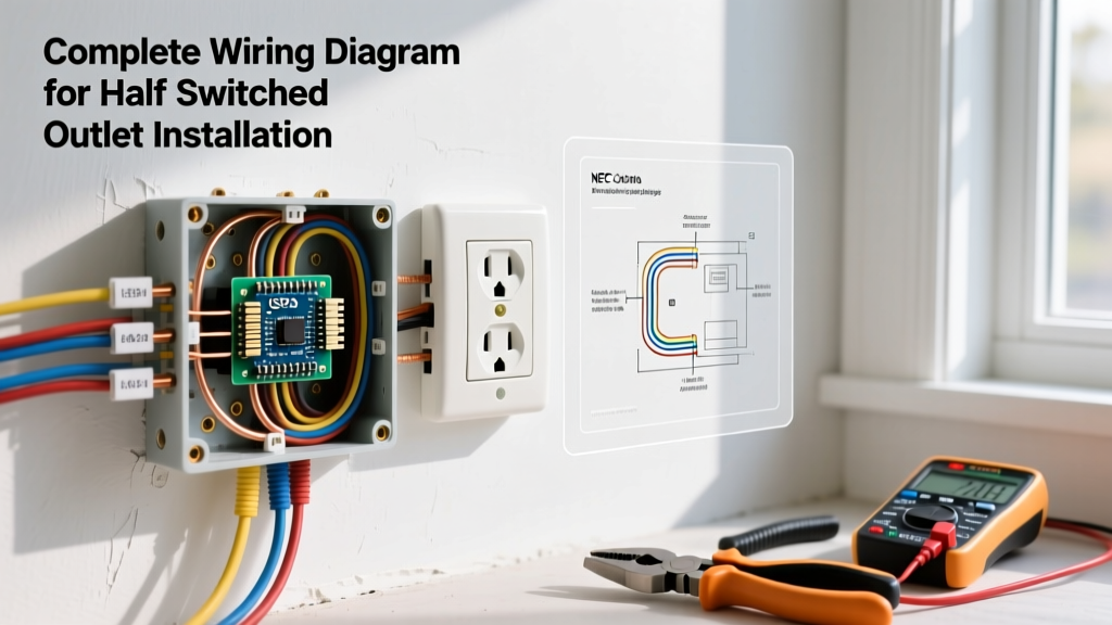
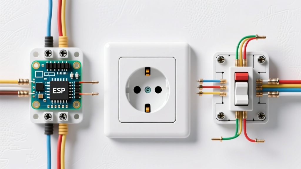
- Check for Split Receptacles: In kitchens and dining areas, duplex receptacles are often split-wired (the brass tab on the hot side is broken off) to allow one half to be switched by a wall switch and the other to remain constantly hot. Ensure the top and bottom halves aren't controlled by a nearby switch you haven't toggled.
Phase 2: Multimeter Deep Dive and Voltage Analysis
Standard three-light receptacle testers (like the $12 Sperry ET64020) are excellent for a quick sanity check, but they cannot quantify voltage drop, identify high-resistance connections, or detect bootleg grounds. To truly conquer the electrical outlet challenge, you need a True-RMS digital multimeter (DMM) rated for CAT III or CAT IV environments, such as the Fluke 117 (retailing around $220 in 2026) or the Klein Tools MM600.
The 3-Point Voltage Test
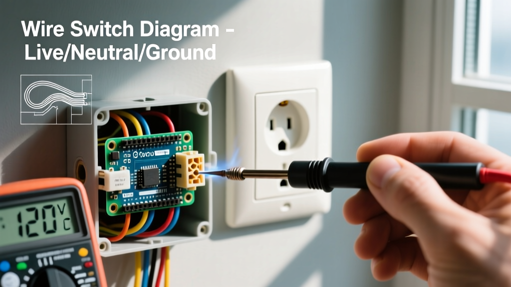
With the DMM set to AC Voltage (V~), insert the probes into the receptacle slots and record the following measurements. Standard US nominal voltage is 120V, with an acceptable ANSI C84.1 range of 114V to 126V.
- Hot to Neutral (H-N): The shorter slot to the longer slot. Should read ~120V.
- Hot to Ground (H-G): The shorter slot to the U-shaped ground pin. Should read ~120V.
- Neutral to Ground (N-G): The longer slot to the ground pin. Should read between 0.5V and 2.0V under normal load conditions. A reading of exactly 0.0V under load can sometimes indicate an illegally bonded neutral and ground at the receptacle (a bootleg ground).
Safety Warning: Never attempt to probe a receptacle with a multimeter if the faceplate is cracked, shows signs of scorching, or if you smell ozone or burning plastic. De-energize the circuit at the panel immediately and consult a licensed electrician. For more on workplace and residential electrical safety standards, refer to the OSHA Electrical Safety guidelines.
Phase 3: Physical Inspection and the Backstab Failure Mode
If your multimeter reads 0V across all three test points, the circuit is open. If it reads 120V H-N but drops to 90V or lower when you plug in a high-wattage load (like a 1500W space heater), you have a high-resistance connection. In 90% of these cases, the culprit is the 'backstab' or push-in wiring method.
The Push-In Terminal Vulnerability
Standard residential-grade receptacles (like the basic Leviton R52-05320-WCP, costing about $1.25) feature push-in terminals on the back. These rely on a tiny internal brass spring clip to bite into the 14 AWG solid copper wire. Over 10 to 15 years, thermal cycling—the expansion and contraction caused by drawing and releasing current—causes these spring clips to lose their tension. The wire remains physically inserted, but the electrical contact area shrinks, creating a micro-arc that generates immense heat and voltage drop.
The Fix: When replacing a failed receptacle, always use the side-wiring terminal screws. Wrap the stripped wire clockwise around the screw so that tightening the screw pulls the wire loop tighter. For a superior connection, upgrade to a commercial/spec-grade receptacle like the Leviton T5262-W or Hubbell 5262A ($4.50 to $6.50), which feature heavy-gauge steel yokes, deeper wire wells, and robust internal brass contacts that maintain blade tension far longer than residential models.
Phase 4: The Diagnostic Matrix
Use this structured matrix to map your multimeter readings and physical observations to the exact root cause of your electrical outlet challenge.
| Symptom / Observation | Multimeter Reading (No Load) | Multimeter Reading (Under 12A Load) | Root Cause Diagnosis | Corrective Action |
|---|---|---|---|---|
| Dead outlet, NCVT shows no voltage | 0V H-N, 0V H-G | N/A | Open Hot (upstream backstab failure or tripped GFCI) | Trace upstream to the previous working receptacle; re-terminate using side-screws or pigtails. |
| Outlet works, but lights dim when vacuum starts | 121V H-N | 104V H-N (Severe Voltage Drop) | High-resistance Neutral connection or loose neutral bus bar | Check neutral pigtail wire nut connection; verify tightness of neutral bar in the sub-panel. |
| Tester shows 'Open Ground', but ground wire is present | 120V H-N, 0V H-G | 120V H-N, 0V H-G | Disconnected ground wire or broken ground path back to panel | Re-terminate ground wire to the green grounding screw on the receptacle yoke. |
| Receptacle faceplate is warm to the touch | 118V H-N | 116V H-N | Internal brass contact fatigue (loose blade tension) causing arcing | Replace receptacle immediately with a spec-grade TR (Tamper Resistant) model. |
| Reversed Polarity indicated by tester | 0V H-N, 120V H-G | 0V H-N, 120V H-G | Hot and Neutral wires swapped on terminal screws | De-energize, swap the black (hot) to brass screw and white (neutral) to silver screw. |
Phase 5: Thermal Imaging and Advanced Edge Cases
For intermittent challenges where the outlet works fine during testing but trips breakers randomly, thermal imaging is the ultimate diagnostic tool. Using a compact thermal camera like the FLIR C5 (approx. $550), scan the receptacle faceplate and the exposed junction box wiring while running a continuous 12-amp load (such as a hair dryer or portable heater) for 15 minutes.
According to the National Fire Protection Association (NFPA) and the National Electrical Code (NEC), any connection point that registers a temperature delta (ΔT) of more than 15°F (8.3°C) above ambient room temperature or adjacent identical components indicates a failing connection requiring immediate remediation. A hotspot on the brass terminal screw usually indicates an improperly torqued screw or stripped threads, while a hotspot on the wire nut indicates inadequate wire stripping or a loose twist.
The 2026 NEC Compliance Check
As you resolve your electrical outlet challenge, ensure your repairs align with current code requirements. The 2026 NEC cycle continues to mandate Tamper-Resistant (TR) receptacles in all dwelling unit areas, including guest rooms and dormitories. Furthermore, AFCI protection is now strictly enforced in virtually all 120V, 15A and 20A branch circuits supplying outlets in living spaces. If you are replacing a receptacle in an older home that lacks an equipment grounding conductor (EGC), you are legally permitted to install a GFCI receptacle marked 'No Equipment Ground' and 'GFCI Protected'—but you must not bridge the neutral to the ground to fake a reading on your tester.
Summary: Methodical Troubleshooting Wins
The electrical outlet challenge is rarely a mystery when approached with the right instruments and a logical sequence. By abandoning guesswork in favor of True-RMS voltage analysis, understanding the mechanical limitations of push-in terminals, and utilizing thermal diagnostics for hidden resistance, you transform a frustrating dead outlet into a straightforward, code-compliant repair. Always prioritize safety, verify your lockout/tagout procedures, and never hesitate to upgrade to commercial-grade components for long-term reliability.