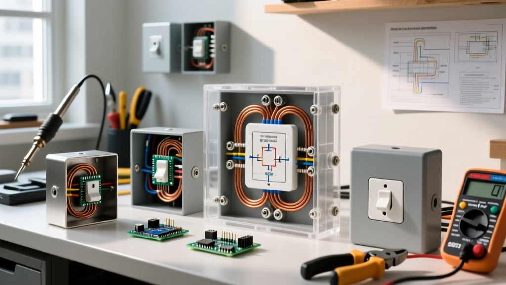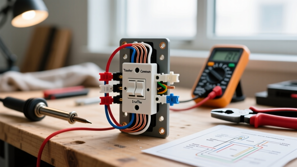

Why Is My Electrical Outlet Not Working? A Diagnostic Approach
When a standard 120V residential receptacle suddenly stops delivering power, the root cause is rarely a mystery to a trained technician, but it can be highly frustrating for a homeowner. A dead outlet is typically the result of a tripped protective device, a failed push-in wire connection, or a compromised neutral path. According to the U.S. Consumer Product Safety Commission (CPSC), electrical receptacles are involved in thousands of residential fires annually, often stemming from high-resistance connections that degrade over time.
This inspection and testing guide moves beyond basic troubleshooting. We will systematically isolate the failure point using industry-standard diagnostic tools, interpret specific voltage readings based on ANSI C84.1 tolerances, and outline the exact repair protocols required by the National Electrical Code (NEC).
Essential Diagnostic Tools for Outlet Testing
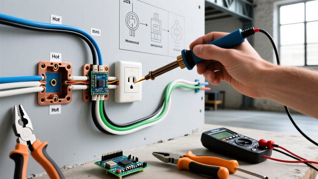
Before opening any junction boxes or removing faceplates, you must verify the electrical state of the circuit. Relying solely on a basic plug-in tester is insufficient for identifying high-resistance faults or bootleg grounds. Here is the professional toolkit required for accurate diagnosis.
| Tool Type | Recommended Model | Avg. Cost (2026) | Primary Diagnostic Use |
|---|---|---|---|
| Non-Contact Voltage Tester (NCVT) | Klein Tools NCVT-2 | $35 - $45 | Verifying presence of voltage before removing the receptacle. |
| Plug-in Circuit Analyzer | Sperry Instruments GFI-3500 | $15 - $25 | Quick identification of wiring faults (open neutral, reverse polarity). |
| Digital Multimeter (DMM) | Fluke 117 True RMS | $190 - $220 | Precise voltage drop testing, continuity checks, and identifying high-resistance neutrals. |
| Receptacle Tension Tester | CMST RT-100 | $40 - $60 | Measuring the physical gripping force of the receptacle contacts on plug blades. |
Phase 1: The 60-Second Visual and GFCI Inspection
Before reaching for a multimeter, perform a rapid visual and upstream inspection. Over 40% of "dead outlet" service calls are resolved in this phase without ever turning off a breaker.
1. Trace the GFCI and AFCI Protection Chain
Modern NEC requirements mandate Ground Fault Circuit Interrupter (GFCI) protection in all wet locations (kitchens, bathrooms, garages, exteriors) and Arc Fault Circuit Interrupter (AFCI) protection in living spaces. A standard outlet in a bedroom may be wired downstream of a GFCI receptacle in an adjacent bathroom or a dual-function AFCI/GFCI breaker in the main panel.
- Action: Check all GFCI receptacles in adjacent rooms. Press the "TEST" button, then the "RESET" button. If the downstream outlet regains power, the upstream GFCI had tripped due to a transient ground fault.
- Panel Check: Inspect your main electrical panel. Look for breakers with a physical "TEST" button (AFCI/GFCI). If the breaker flag is in the middle (tripped) position, turn it fully OFF, then firmly push it to ON.
2. Inspect for Thermal Damage
Remove any plugged-in devices and examine the receptacle slots. Look for brown scorch marks, melted plastic, or a distinct ozone/burning plastic odor. If you observe thermal damage, stop immediately. This indicates a high-resistance connection that has been arcing. The receptacle must be replaced, and the wire insulation must be inspected for brittleness.
Phase 2: Deep Diagnostics with a Digital Multimeter
If the breaker is on and no GFCI has tripped, the circuit is open somewhere between the panel and the receptacle. A plug-in analyzer might show "Open Hot" or "Open Neutral," but it cannot tell you why or where. A True RMS Digital Multimeter (DMM) is required to measure exact voltage potentials.
Safety Warning: The Occupational Safety and Health Administration (OSHA) strictly mandates treating all unverified circuits as energized. Always wear safety glasses and ensure your multimeter is rated CAT III 600V or higher before probing live terminals.
The 3-Point Voltage Matrix
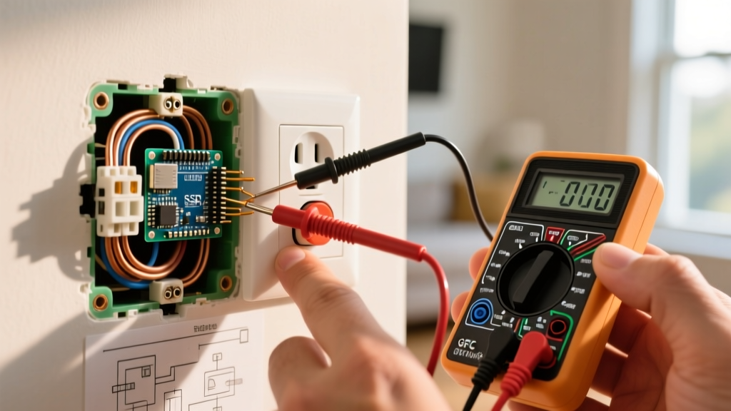
Set your DMM to AC Voltage (V~). Insert the black probe into the COM port and the red probe into the V/Ω port. Test the following three points at the dead receptacle (or the nearest live receptacle on the same circuit if the dead one has zero voltage).
| Test Points | Expected Reading (ANSI C84.1) | Fault Indication if Abnormal |
|---|---|---|
| Hot (Short Slot) to Neutral (Long Slot) | 114V - 126V | Zero: Open hot or open neutral upstream. Low (e.g., 90V): High-resistance connection or severe voltage drop. |
| Hot (Short Slot) to Ground (U-Shape) | 114V - 126V | Zero: Open hot upstream, or missing equipment ground. Lower than H-N: High-resistance ground path. |
| Neutral (Long Slot) to Ground (U-Shape) | 0V - 2V | ~120V: Bootleg ground (neutral tied to ground downstream) or open neutral with a load connected. High (5V+): Overloaded neutral or loose neutral bus bar connection. |
Interpreting the "Backstab" Failure Mode
If your Hot-to-Neutral reading fluctuates or reads zero, but Hot-to-Ground reads a solid 120V, you have an Open Neutral. In homes built between 1970 and 2010, this is almost always caused by a failed "backstab" (push-in) wire connector on the back of a builder-grade receptacle. These spring-loaded clips lose tension over years of thermal expansion and contraction from electrical loads. The Fix: Cut back the wire to fresh copper, strip 3/4 inch of insulation, and terminate the wires using the side-binding screw terminals or, preferably, a WAGO 221 lever-nut pigtail connection.
Phase 3: Edge Cases and Advanced Failure Modes
When standard testing does not reveal the issue, you must investigate less common but highly dangerous failure modes.
1. The Multi-Wire Branch Circuit (MWBC) Disconnect
If the dead outlet is in a kitchen or older home, it may be part of a split-receptacle MWBC (two hot wires sharing one neutral). If an electrician previously replaced the breaker and removed the handle tie, or if one leg of the MWBC tripped, half the outlet will be dead while the other half works. Furthermore, if the shared neutral wire is disconnected at a downstream junction box while both hots are energized, the neutral can carry 240V, instantly destroying plugged-in electronics.
2. Aluminum Wiring Oxidation (Pre-1972 Homes)
If you remove the receptacle and discover dull, silver-colored wire, you have aluminum branch circuit wiring. Aluminum oxidizes rapidly when exposed to air and expands at a different rate than copper, leading to loose terminations and fires. You cannot simply attach aluminum wire to a standard copper-rated receptacle. You must use CO/ALR rated devices or, ideally, pigtail the aluminum to copper using AlumiConn lug connectors or the COPALUM crimp system before terminating at the receptacle.
Repair Scenarios and Cost Breakdown
Understanding the financial scope of your repair helps you decide whether to DIY or hire a licensed professional. Below is a realistic cost matrix for 2026.
| Identified Issue | Required Repair Protocol | DIY Material Cost | Pro Electrician Cost |
|---|---|---|---|
| Tripped GFCI/AFCI | Reset device; identify moisture/arc source. | $0 | $125 - $175 (Diagnostic fee) |
| Failed Backstab Connection | Cut, strip, and pigtail with WAGO 221 connectors. | $5 - $10 | $150 - $225 |
| Burnt/Melted Receptacle | Replace with commercial-grade spec receptacle (e.g., Leviton 5362). | $4 - $8 | $150 - $250 |
| Severed Wire in Wall | Fish new NM-B cable or install an accessible junction box. | $20 - $40 | $300 - $600+ |
When to Abandon DIY and Call a Professional
While replacing a standard receptacle is a foundational DIY skill, certain symptoms indicate systemic panel or wiring hazards that require a licensed electrician. Do not attempt to troubleshoot further if you encounter:
- Buzzing or Hissing from the Panel: This indicates a loose main lug or a failing breaker bus stab, which can lead to an arc flash.
- Repeated Breaker Tripping: If a breaker trips immediately upon resetting with no load plugged in, you have a hard dead short or a degraded breaker mechanism. Forcing it to stay on violates basic safety protocols and risks structural fire.
- Knob-and-Tube or Degraded Cloth Wiring: If you open the wall box and find brittle cloth insulation crumbling off the conductors, the entire circuit likely requires rewiring. Disturbing it can cause shorts inside the wall cavity.
By methodically applying these diagnostic steps, you can accurately determine why your electrical outlet is not working, ensure your repairs meet modern safety codes, and restore reliable power to your home.